ULN2003 Pinout Diagram and Connection with Arduino
Hi, in this article, we are going to see the Stepper Motor Driver ULN2003 Pinout Diagram. Also, we will see the connection diagram for interfacing the ULN2003 with Arduino. It is a popular module used for driving small stepper motors. It supports motor driving voltages from 5V to 12V. It has LED Indication Lights for each channel to visualize the motor steps during operation. The ULN200 is built with a Darlington transistor array with seven channels for control signals, but when it is used for controlling a stepper motor only four channels are used.
ULN2003 Pinout Diagram
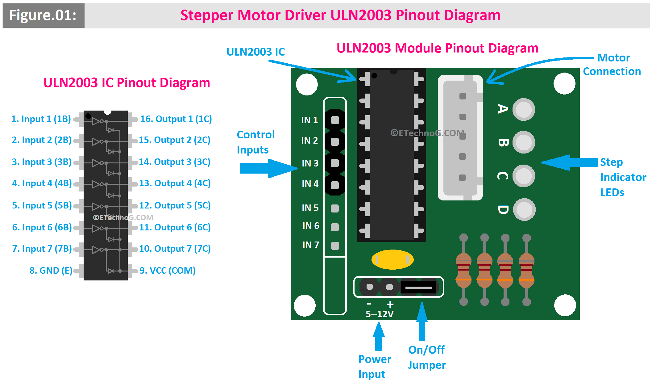
Here, you can see the pinout diagram of both ULN2003 IC and ULN2003 Module.
As you can see the ULN2003 IC is a standalone 16-pin IC (Integrated Circuit) that contains seven Darlington transistor pairs on the other hand the ULN2003 module basically a breakout board that houses the ULN2003 IC and some additional components and connectors which are pre-wired and designed for easier use.
ULN2003 IC Pinout
Pin No. 1 - 1B(Input Channel 1)
Pin No. 2 - 2B(Input Channel 2)
Pin No. 3 - 3B(Input Channel 3)
Pin No. 4 - 4B(Input Channel 4)
Pin No. 5 - 5B(Input Channel 5)
Pin No. 6 - 6B(Input Channel 6)
Pin No. 7 - 7B(Input Channel 7)
Pin No. 8 - GND(Ground)
Pin No. 9 - Common(Common cathode for freewheeling diodes (connect to motor power supply voltage)
Pin No. 10 - 7C(Output Channel 7)
Pin No. 11 - 6C(Output Channel 6)
Pin No. 12 - 5C(Output Channel 5)
Pin No. 13 - 4C(Output Channel 4)
Pin No. 10 - 3C(Output Channel 3)
Pin No. 10 - 2C(Output Channel 2)
Pin No. 10 - 1C(Output Channel 1)
ULN2003 Module Pinout
Input Pins (IN1-IN4): These pins are needed to connect to the control pins of a microcontroller like Arduino.
Output Pins (OUT1-OUT4): These are needed to connect to the coils of the stepper motor by matching with the stepper motor windings.
VCC: Power supply for the motor (typically 5V or 12V, depending on the motor).
GND: Ground connection, common with the microcontroller and the motor power supply.
Common (COM): This is connected to the motor power supply and is internally linked to the freewheeling diodes, protecting the circuit from back EMF.
Stepper Motor Driver ULN2003 Connection with Arduino
Here, you can see the connection diagram for ULN2003 interfacing with Arduino.
Connection Description
- You can see the IN1, IN2, IN3, and IN4 terminals of the ULN2003 Module are connected to the digital output pins(8, 9, 10, and 11) of the Arduino Module.
- The stepper motor terminals(Common, Coil 1, Coil 2, Coil 3, and Coil 4) are connected to the Output Terminals of the ULN2003 Module.
- A 5-12V DC power supply should be provided to the power input terminal of the ULN2003 Module.
Working Principle
The ULN2003 is a transistor array that basically acts as a switch. It drives the current required for the stepper motor's coils. It converts the low-current signals from the Arduino to the higher current required by the motor. So when the Arduino sends signals to the ULN2003 to energize the coils in the correct order to control the motor's rotation and direction, the ULN2003 simplifies the process by providing a direct interface to the motor's coils so the stepper motor moves in steps when its coils are energized in a specific sequence.
Read Also:
ULN2003 Pinout Diagram and Connection with Arduino
 Reviewed by Author
on
January 28, 2025
Rating:
 Reviewed by Author
on
January 28, 2025
Rating:


