Cam Switch, Rotary Switch, and Selector Switch Connections
Here, in this article, we are going to see the connection diagram and wiring procedure for the Cam Switch, Rotary Switch, and Selector Switch. All of these switches look almost the same. There are very minor differences between them. Cam Switch is primarily used for sequential control of machinery and industrial processes, that involve heavy loads and complex sequences of operations.
The Rotary Switch is used for selecting between different options or settings, such as speed, temperature, or input sources, in a wide range of devices and applications. A Selector Switch is a specific type of rotary switch designed for mode or function selection, commonly used in control panels and machinery to choose between different operational modes or states.
There are different types of selector switches such as Simple On/Off selector switches, 3-position switches, Three Phase switches, 4 Position switches, 8-Terminal switches, 12-Terminal switches, 16-Terminal switches, and many more. Here, we are going to see the connection diagram of these switches for different electrical circuits.
Simple On/Off Selector Switch Connection Diagram
Here, you can see the connection diagram of a simple On/Off Selector Switch.
This type of switch has two terminals like an SPST switch. We just need to connect this switch in series between the power source and the load. When we keep the switch in the Off position it makes an open circuit so no current can flow through it but when we keep the switch in the On position, it makes a closed circuit and the current can flow through it.
As you can see here in the above diagram we have used a light bulb as a load. You can see we have connected the neutral terminals of both the light and the power source directly but the phase terminal is connected in series with the switch. So, if we keep the switch in the Off position, the light will be in Off condition but if we keep the switch in the On position the light will glow.
3 Position Selector Switch or Rotary Switch Wiring Diagram
Here in the below wiring diagrams, you can see the connection procedure and working principle of a 3-position Selector Switch or Rotary Switch.
As you can see it has three terminals generally, identified as 1, 0, 2. Terminal '0' should be connected to the power source and terminals '1' and '2' should be connected to two different loads or circuits. When we keep the knob of the switch in position "0" or "Off", there will be no contact between those terminals. When we keep the knob in position '1' the input terminal will be contacted to the output terminal "1" and when we keep the knob in position '2' the input terminal will be contacted to the output terminal "2".
As per the above diagram, when we keep the switch in the '0' position no lamp will glow. When we keep the switch in position '1' the lamp 1 will glow and when we keep the switch in position '2' the lamp 2 will glow.
3-Phase Rotary Selector Switch Wiring Diagram and Connection Procedure
A 3-phase rotary selector switch is used to control and select between different phases or positions in a 3-phase electrical circuit. This type of switch is commonly used in industrial and commercial applications where three-phase power distribution is required.
Here, in the below diagram, we have shown the connection diagram of a single standalone 3-phase rotary selector switch and we have also shown a changeover circuit using three 3-phase rotary switches.
As you can see in the above diagram, the 3-phase selector switch has four positions - Off, R, Y, and B. Also, they have four terminals. Here, one terminal is for output and the other three terminals are for three-phase input.
When we keep the knob of the switch in the Off position, no current flows through the switch. When we keep the knob on any one phase, that phase will be connected to the output. For example, if we keep the knob on the "B" phase then the output load will be connected to the "B" phase of the three-phase power source.
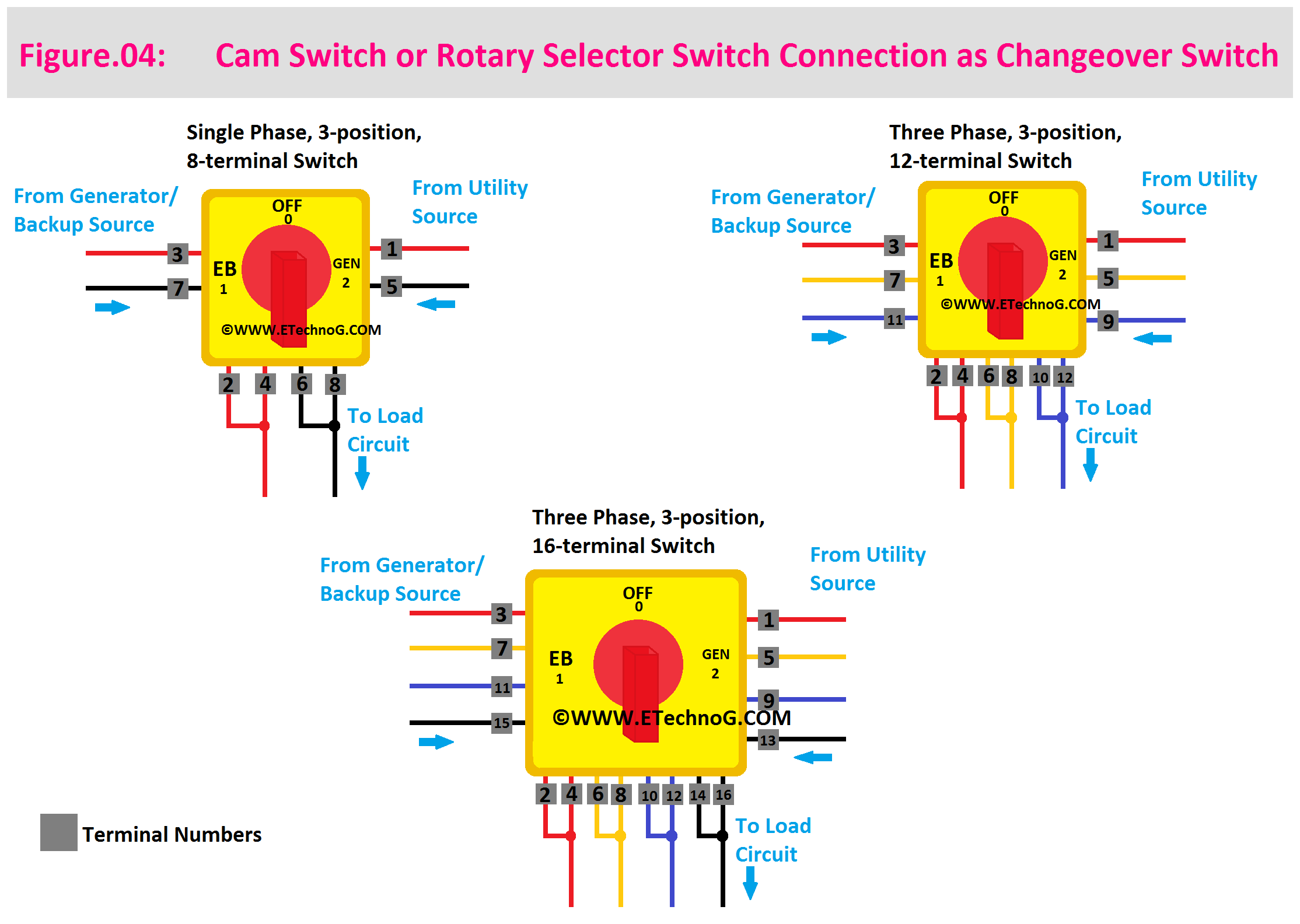
Cam Rotary Changeover Switch Connection
Here, you can see the connection of different types of Cam Rotary Changeover Switches such as -
- Single Phase, 3-Position, 8-Terminal Switch
- Three Phase, 3-Position, 12-Terminal Switch
- Three Phase, 3-Position, 18-Terminal Switch
Read Also:
- Ammeter Connection Diagram with Selector Switch and CT
- Voltmeter and Selector Switch Connection for Three (3) Phase Supply
- Double Motor Control with Selector Switch Connection
- Single Phase ATS(Automatic Transfer Switch) Wiring Diagram and Connection
- 3 Phase ATS(Automatic Transfer Switch) Wiring Diagram and Connection


