8-Pin Relay Pinout, Circuit, and Wiring Diagram
Hey, in this article, we are going to see the 8-pin Relay Pinout, Circuit, and Wiring Diagram. We will learn about plug-in relay or PLA relay that is used in different electrical circuits. An 8-pin relay is also known as 2C/O Relay which means 2 commons and outputs. This type of relay is generally used with a relay base. We need to plug in the relay to the base. Actually, an 8-pin relay typically refers to the pin configuration of the relay socket or base. These relays can be of various types, including SPDT (Single Pole Double Throw) or DPDT (Double Pole Double Throw). The 8-pin configuration typically includes pins for coil connections (usually two or more pins) and pins for the common, normally open, and normally closed contacts.
Pinout Diagram
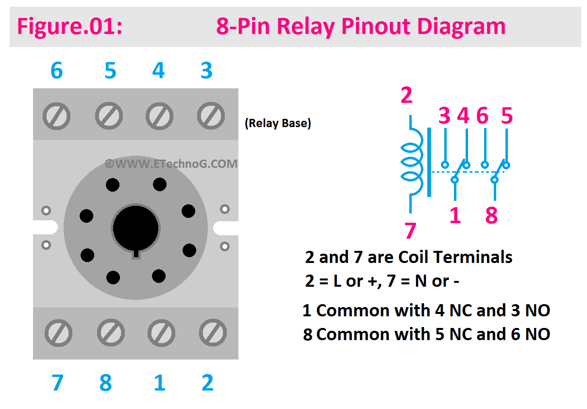
Here, you can see the Pinout Diagram of an 8-pin PLA-type relay.
As this type of relay is used with a Relay base, we need to learn the pinout of that 8-pin relay base. Here is the pin configuration or pin details are explained below,
Coil Pins: Pin no. 2 and Pin no.7 of the relay are the Coil Pins where Pin no. 2 is Line or Positive and Pin no.7 is the Neutral or Negative. These pins are used to connect the control signal (voltage) that activates the relay coil. When the coil is energized it generates a magnetic field that switches the relay contacts.
Common (COM): This relay has two separate common terminals with their own NO and NC terminals. 1 and 8 are the two separate common terminals. These pins are the common connection for the relay contacts. They are typically connected to one side of the load (e.g., a motor, lamp, or another device).
Normally Open (NO): Pin no. 3 is the NO terminal for common pin 1 and Pin no. 6 is the NO terminal for common pin 8. These pins are the normally open contact of the relay. When the relay is not energized, these contacts remain open and keep interrupting the circuit. When the relay is energized, these close the circuit.
Normally Closed (NC): Pin no. 4 is the NC terminal for common pin 1 and Pin no. 5 is the NC terminal for common pin 8. These pins are the normally closed contact of the relay. When the relay is not energized, these contacts are closed, allowing current to flow through the circuit. When the relay is energized, these open the circuit.
Wiring Diagram
Here, in the below wiring diagram, you can see we have used an 8-Pin Relay to control four differents.
According to the above wiring diagram, two lights will glow at the same time. When the switch(connected to the relay coil) is turned On Bulb 1 and Bulb 4 will glow as they are connected to NO terminals but when the switch is turned Off Bulb 2 and Bulb 3 will glow as they are connected to NC terminals.
Latching or Holding Circuit using an 8-pin Relay
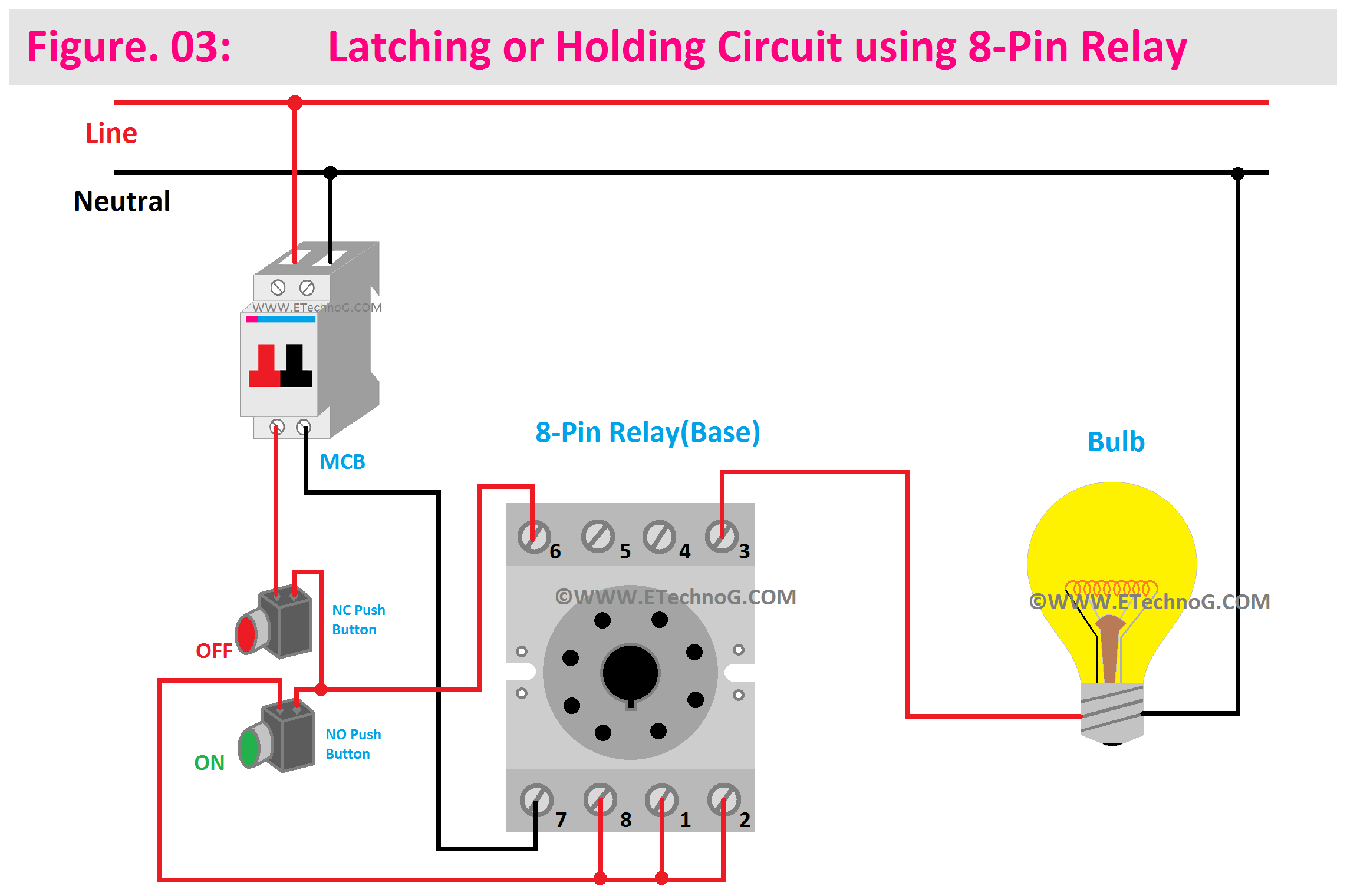
Here, you can see the circuit diagram for Latching or Holding Circuit using an 8-pin Relay.
This type of circuit you can use for single-phase motor control. Here, we have used two push-button switches. When we push the green color NO push button switch the load (light or motor) will activate and it will keep On until we push the red color NC Push button switch.
Read Also:
8-Pin Relay Pinout, Circuit, and Wiring Diagram
 Reviewed by Author
on
October 16, 2023
Rating:
 Reviewed by Author
on
October 16, 2023
Rating:


