Understand Rod Earthing with Picture and Constructional Diagram
Here, in this article, we are going to understand the Rod Earthing with diagrams so it will help us to easily understand its different parts, installation procedure, etc.
Rod Earthing is the simplest type of earthing. It is also known as ground rod installation or grounding electrode system. It is a very common method used to establish an effective electrical grounding connection for various systems, including buildings, power distribution systems, and electronic equipment.
The purpose of rod earthing is to provide a safe path for electrical fault currents or leakage currents to flow into the ground. It also helps to prevent the buildup of dangerous electrical potentials due to accidental electrical faults that reduce the risk of electrical shock and damage to equipment.
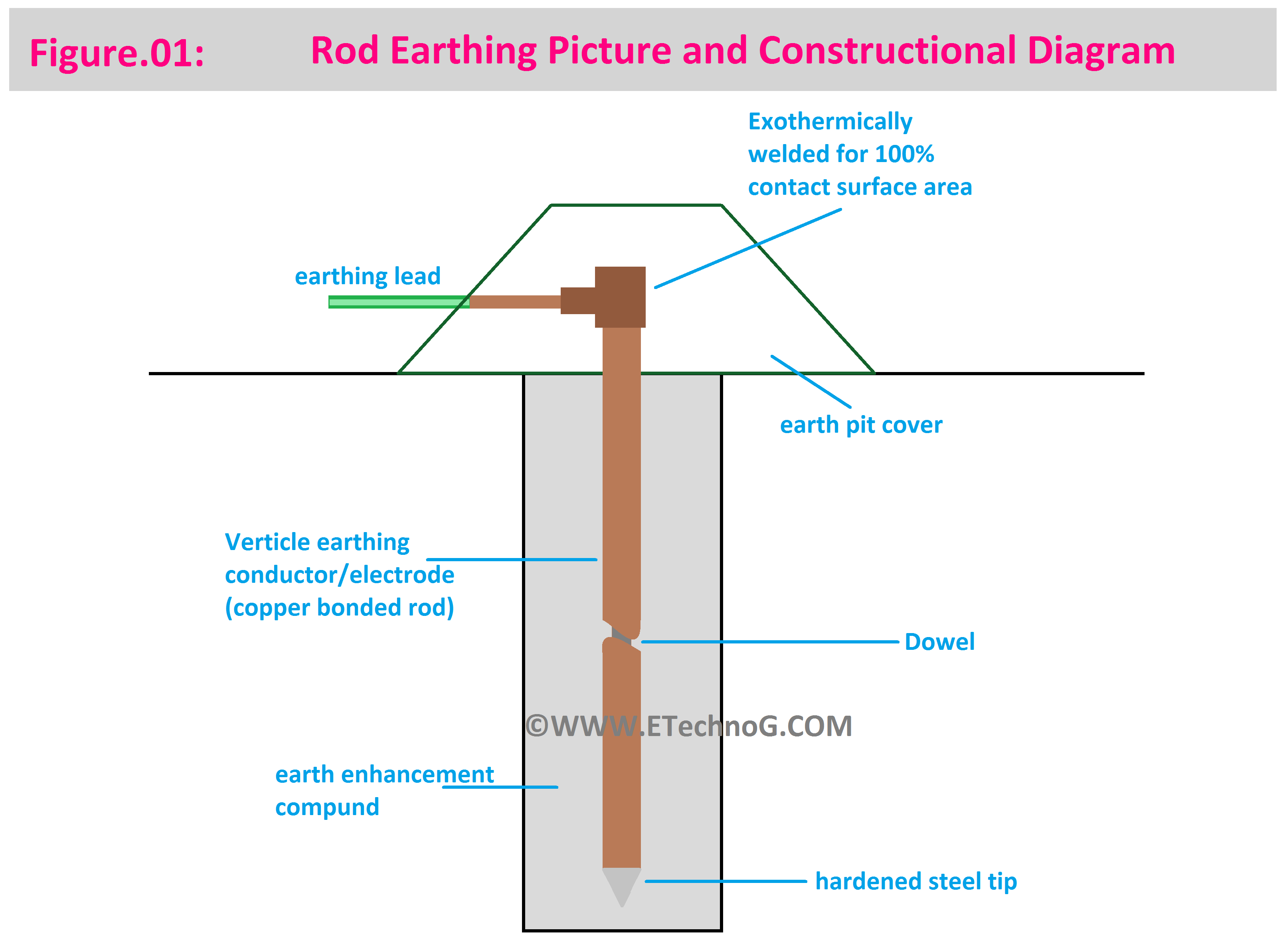
First of all, let's see the Rod Earthing Picture that shows the different constructional parts.
- What is Plate Earthing? Diagram, Applications, Procedure
- What is Common Grounding? Examples, Advantages
- What is Ground Fault Circuit Interrupter(GFCI)? Use
- Main Purpose of Using Neutral Grounding Resistor
- Difference between Earth Fault Relay and Earth Leakage Relay
The above diagram shows a rod earthing installation with copper material. The structure of the earthing system for other types of materials is the same. There may be a little difference in the electrode or grounding rod due to different types of materials.
Here are some materials that are used for rod earthing,
Copper: Copper is one of the most widely used materials for grounding rods due to its excellent conductivity and corrosion resistance. It provides a very low-resistance path for electrical currents to flow into the ground, ensuring effective grounding.
Galvanized Steel: Galvanized steel rods are coated with a layer of zinc to protect against corrosion. They are commonly used for grounding applications, especially in areas with harsh soil conditions.
Stainless Steel: Stainless steel rods are highly resistant to corrosion, making them suitable for corrosive environments. They are durable and provide a long-lasting grounding solution.
Copper-Bonded Steel: These rods have a steel core with a layer of copper bonded to the surface. They combine the benefits of both copper and steel, offering good conductivity and corrosion resistance.
Copper-Clad Steel: Similar to copper-bonded steel, these rods have a layer of copper cladding over a steel core. They provide a cost-effective solution with reasonable conductivity and corrosion resistance.
Aluminum: Aluminum rods are lighter than copper rods and can be cost-effective. However, aluminum is not as conductive as copper, so larger-sized rods might be necessary to achieve the desired grounding performance.
Bronze: Bronze rods are a blend of copper and other metals, providing good conductivity and corrosion resistance. They are commonly used in some grounding applications.
Now, let's understand the different parts of a Rod Earthing system that are shown in the above diagram,
Electrode: It is also known as a Grounding Rod. An electrode is a conductive element (usually a metal rod) that is buried in the ground and electrically connected to the system that needs to be grounded. The most common type of grounding electrode is a metal rod made of copper or galvanized steel, typically 8 to 10 feet in length and around 5/8 to 3/4 inches in diameter.
The grounding rod is installed vertically into the earth at a depth where it can make good electrical contact with the moist soil. It's important that the rod is placed in an area with good soil conductivity to ensure a low-resistance path to the ground. The moisture content of the soil surrounding the rod helps to create a low-resistance path for electrical currents to flow from the system into the ground.
Earth Pit Cover: An earth pit cover is also known as a grounding pit cover or earthing pit cover. It is a protective lid or cap used to cover the opening of an earth pit or grounding electrode pit.
Earthing Lead: The earthing lead is a conductive cable or wire that connects the grounding electrode to the electrical system or equipment that needs to be grounded. The conductor is typically made of copper or aluminum, as these materials offer good conductivity and corrosion resistance. The size of the earthing lead depends on factors such as the magnitude of the electrical currents and the distance between the grounding electrode and the equipment. The rod is connected to the grounding conductor of the electrical system or equipment using a suitable connector.
Thank you for visiting the Website. Keep visiting for more Updates.

