Sub Panel Wiring Diagram and Connection with Main Panel
Hey, in this article, we are going to see different types of sub-panels (120V, 240V, etc) wiring diagrams, and connections with the Main Panel. A main panel and a sub-panel are both important components of an electrical distribution system.
The main panel is the primary electrical distribution point in a building or any other distribution area. It is usually located where the main electrical service enters the building, often on an exterior wall or in a utility room. The main panel receives the main electrical supply from the utility company's service lines and is equipped with a main disconnect breaker. This main disconnect breaker allows you to shut off power to the entire building in case of emergencies or maintenance.
On the other hand, A sub-panel is an additional panel that is connected to the main panel. It is used to distribute power to specific areas or sections of a building that are located far away from the main panel or require their own localized distribution. Sub-panels are fed from the main panel through dedicated feeder wires. They have their own set of circuit breakers to protect the circuits they serve. They are generally smaller than the main panel and have a lower capacity. The capacity of a sub-panel is determined by the rating of the feeder wires connecting it to the main panel.
**Remember that here we have taken random ratings for the panels, and circuit breakers to explain the connection between them. You may need different ratings, so design your system with proper ratings as per your requirements**
240V Sub Panel Wiring Diagram and Connection with Main Panel
Here, you can see the wiring diagram where a 240V Sub Panel is connected to a Main Panel.
Connection Procedure
- Here, we have used a 240V Sub panel that has three circuit breakers with 50A ratings. So we need to connect the Sub Panel to a 240V, Double Pole 150A, or 200A circuit breaker in the main panel.
- So two hot input lines of the sub-panels are connected to a 200A breaker in the main panel.
- Here, we do not need the neutral connection from the main panel to the sub-panel as we need 240V.
- Here we have connected the ground wire from the sub-panel to the ground busbar in the main panel. Remember that if the distance between the main panel and subpanel is greater than 140 feet, you may connect the ground to the nearest ground wire instead of laying a long cable from the Main Panel to the subpanel.
- Now we can connect any load to any one of the circuit breakers in the sub panel.
120V Sub Panel Wiring Diagram and Connection with Main Panel
Here, you can see the wiring diagram where a 120V Sub Panel is connected to a Main Panel.
Connection Procedure
- Here, we have used a 120V sub-panel that has normal circuit breakers such as MCB and GFCI breakers. The total current rating of this panel is 135A.
- The Hot or phase input line from the sub-panel is connected to a 120V single-pole circuit breaker in the main panel.
- The neutral from the sub-panel is connected to the neutral busbar in the main panel.
- The ground wire from the sub-panel is connected to the ground busbar in the main panel.
- The normal 120V supply can be taken from the normal circuit breaker in the sub-panel.
- And GFCI-protected supply can be taken from the GFCI breaker in the sub-panel.
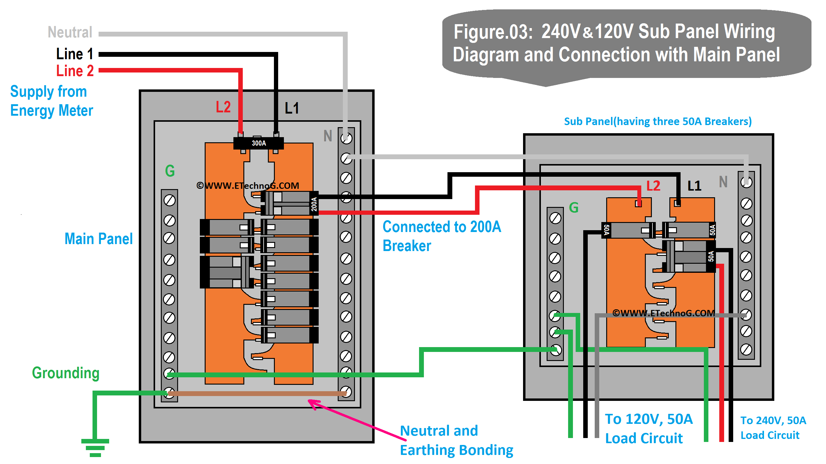
240V / 120V Sub Panel Wiring Diagram and Connection with Main Panel
Here, you can see the wiring diagram where a 240V cum 120V Sub Panel is connected to a Main Panel. The sub-panel will distribute both 240V and 120V supplies.
Connection Procedure
- Here, we have used a 240V cum 120V sub-panel that has a total current rating of 150A.
- So, both hot input lines from the sub-panel are connected to a 240V double pole, 200A circuit breaker in the main panel.
- The neutral from the sub-panel is connected to the neutral busbar in the main panel.
- The ground wire from the sub-panel is connected to the ground busbar in the main panel.
- Now, the 120V supply can be obtained by taking the hot or line wire from a single pole circuit breaker and the neutral line in the sub-panel.
- The 240V supply can be obtained by taking both hot or phase lines from the double pole circuit breaker in the sub-panel.
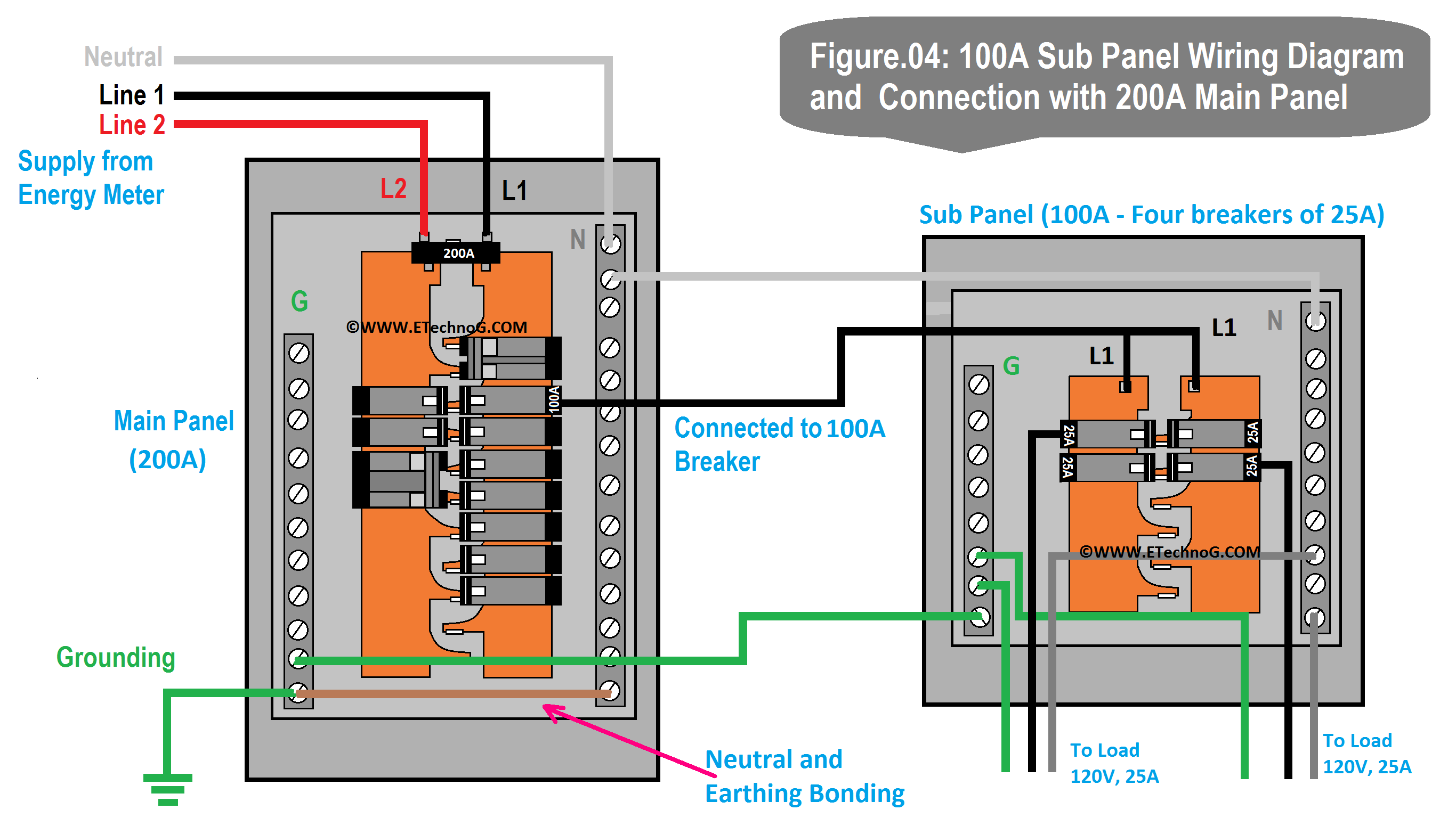
100A Sub Panel Wiring Diagram and Connection with 200A Main Panel
Here, you can see the wiring diagram where a 120V, 100A Sub Panel is connected to a 200A Main Panel.
Connection Procedure
- Here, we have used a 120V,100 Asub-panel, so the input Hot input line from the sub-panel is connected to a 120V, 100A single-pole circuit breaker in the main panel.
- The neutral from the sub-panel is connected to the neutral busbar in the main panel.
- The ground wire from the sub-panel is connected to the ground busbar in the main panel.
- Now, the 120V supply can be obtained by taking the hot or phase line from a single pole circuit breaker and the neutral line in the sub-panel.
- The sub-panel has four circuit breakers of 25A each. So a maximum 25A load can be connected to each breaker.
Read Also:
Thank you for visiting the Website. Keep visiting for more Updates.


