Pilot Switch Wiring Diagram and Connection Procedure
In this article, we are going to see the different types of pilot switch wiring diagrams and connection procedures. Like a regular switch, a pilot switch also allows you to control the flow of electrical current to a connected load, such as a light fixture, fan, or other electrical device. When you toggle the switch to the ON position, the connected load receives power; when you toggle it to the OFF position, the power is cut off.
Just the difference it includes a built-in neon light indicator. This neon light is wired in parallel with the load that the switch controls. When the switch is turned ON and the load is powered, the neon light also receives a small amount of current and starts to glow, indicating that the circuit is active. When the switches are turned OFF, and the load is disconnected from the power supply the neon indicator also be turned OFF which indicates that the circuit is inactive.
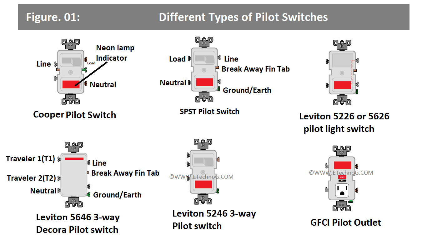
Different Types of Pilot Switches
Here, you can see the diagrams and terminal identifications of different types of Pilot Switches. Here, you can see the Neon Pilot Light Switches, SPST Switch, Two-Way Switch, and Three-Way Switch.
As you see in the above diagram, Cooper and Leviton pilot light switches have the same terminals but their positions opposite to each other. For example, the copper pilot switch has the line input terminal on the left side, load, and neutral terminals on the right side, and the ground terminal available on the right-middle side.
On the other hand, the Leviton pilot switch has the Line terminal on the right side, load, and neutral terminals on the left side, and the ground terminal on the right bottom side. So, it is recommended to always refer to the user manual of the specific pilot switch or any other switch before installation or consult a licensed and professional electrician.
Cooper Pilot Switch Wiring Diagram
Here, you can see the wiring diagram of a Cooper Pilot Switch that is connected to a light bulb.
Connection Procedure
1. Connect the neutral terminal of the light to the neutral terminal of the power source and the neutral terminal of the pilot switch. The right-side bottom terminal is the neutral terminal.
2. Connect the line terminal of the power source to the line terminal of the pilot switch. The left side top terminal is the line terminal.
3. Connect the phase terminal of the light to the Load terminal of the pilot switch. The right side top terminal is the load terminal.
4. Connect the ground wire to the ground terminal of the pilot switch and to the light enclosure if it has a grounding point. The right-side middle terminal is the ground terminal.
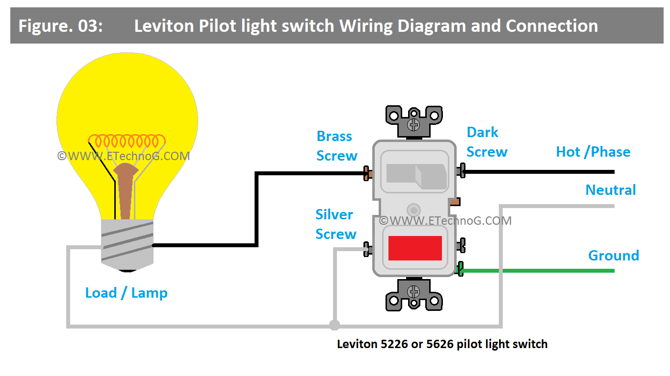
Leviton Pilot Switch Wiring Diagram
Here, you can see the wiring diagram of a Leviton Pilot Switch that is connected to a light bulb.
Connection Procedure
1. Connect the neutral terminal of the light to the neutral terminal of the power source and the neutral terminal(left side bottom) of the pilot switch.
2. Connect the line terminal of the power source to the line terminal(right side top) of the pilot switch.
3. Connect the phase terminal of the light to the Load terminal(left side top) of the pilot switch.
4. Connect the ground wire to the ground terminal(right side bottom) of the pilot switch and to the light enclosure if it has a grounding point.
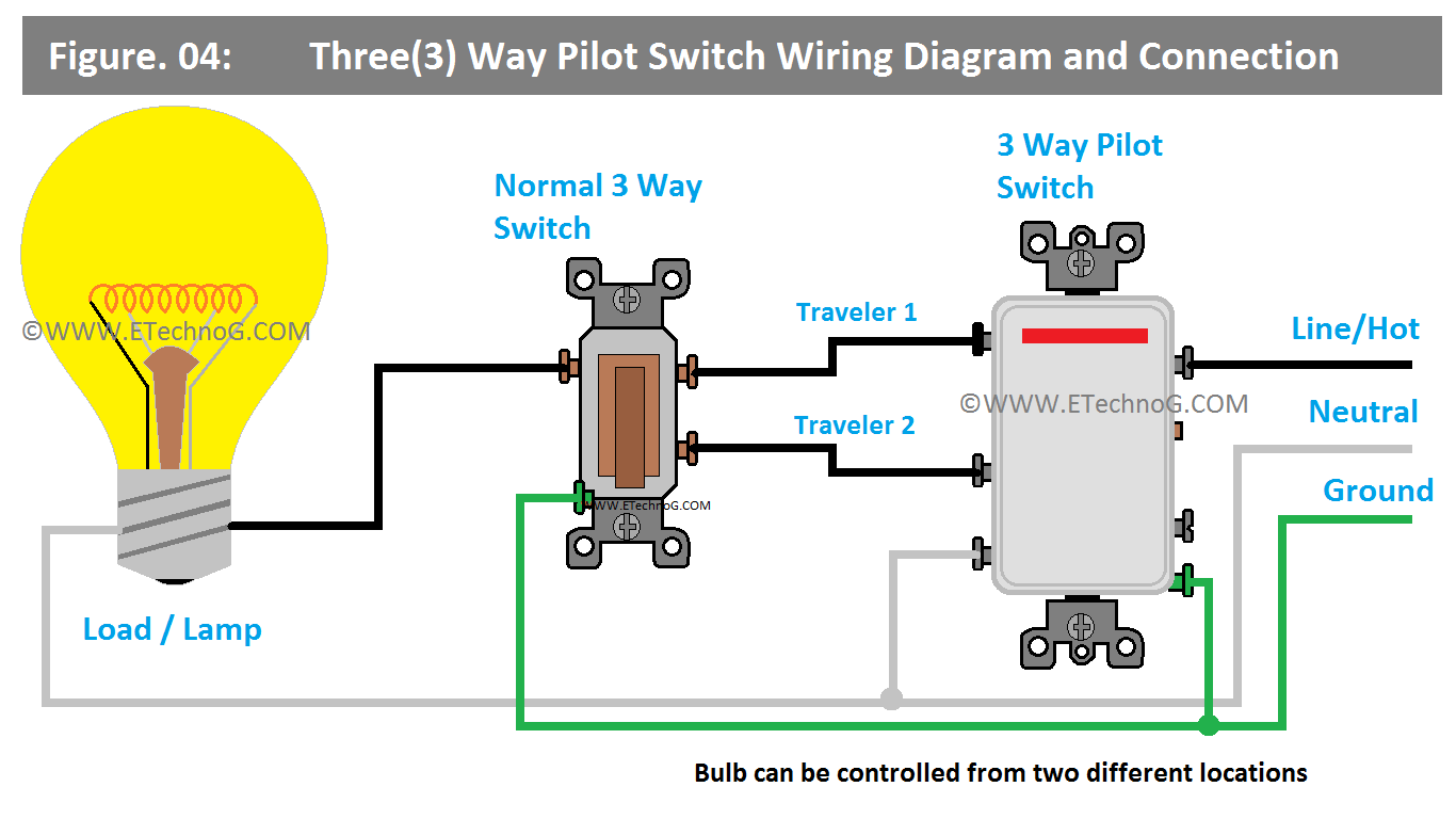
Three(3) Way Pilot Switch Wiring Diagram
Here, you can see the wiring diagram of a 3-way pilot switch that is connected to an ordinary three-way switch and a light bulb. This arrangement allows us to control the light from two different places.
Connection Procedure
1. Connect the neutral terminal of the light to the neutral terminal of the power source and the neutral terminal(left side bottom) of the 3-way pilot switch.
2. Connect the line terminal of the power source to the line terminal(right side top) of the 3-way pilot switch.
3. Connect the Traveler 1(left side top) and Traveler 2(left side middle) terminals of the 3-way pilot switch to the Traveler 1(right side top) and Traveler 2(right side bottom) terminals of the ordinary 3-way switch.
4. Now connect the Line terminal of the Light to the Common Terminal(left side top) of the ordinary 3-way switch.
5. Connect grounding to all the switches and lights if they have grounding terminals.
Pilot Switch Connection with Pilot GFCI
The Pilot GFCI is a Ground Fault Circuit Interrupter (GFCI) with a built-in indicator or pilot light. The pilot light serves as a signal to show whether the GFCI is active and protecting the circuit as intended.
When the GFCI is in normal operation and the circuit is functioning properly, the pilot light is usually turned on. This indicates that the GFCI is active and provides protection.
When the GFCI trips due to a ground fault, the pilot light typically turns off. This visual change in the pilot light's status indicates that there is a fault in the circuit and that the GFCI has successfully interrupted the power to prevent any potential danger.
After the ground fault has been addressed and the issue resolved, the GFCI can be reset. Resetting the GFCI restores power to the circuit, and if there are no ongoing ground faults, the pilot light should turn back on, indicating that the GFCI is once again active and protecting the circuit.
Here, you can see the connection diagram of a Pilot GFCI with Two Pilot Switches and a light bulb.
The connection procedure is very simple, Connect the Pilot GFCI in a similar way you connect an ordinary GFCI. Then connect the output of the Pilot GFCI to the input of the Pilot Switch circuit. And the Pilot switch circuit we have already explained above.
Read Also:


