Master Switch Connection Diagram with Two Way Switches
In this article, we are going to see Master Switch Connection Diagram and wiring procedure. A master switch, also known as a main switch or master control switch, is a single switch that controls the power supply to multiple electrical circuits or devices simultaneously. It acts as the primary control point for turning on or off the entire electrical system or a specific group of devices connected to it.
It is commonly used in various electrical installation systems such as homes, offices, and institutions, to control lighting, appliances, or electrical circuits with a single switch for added convenience and energy efficiency.
In some installations such as hostel lighting systems, we use a master switch with two ways switches, where two-way switches allow the user to control power from different places, and the master switch allows to control power to the whole system from a central location.
Connection Diagram
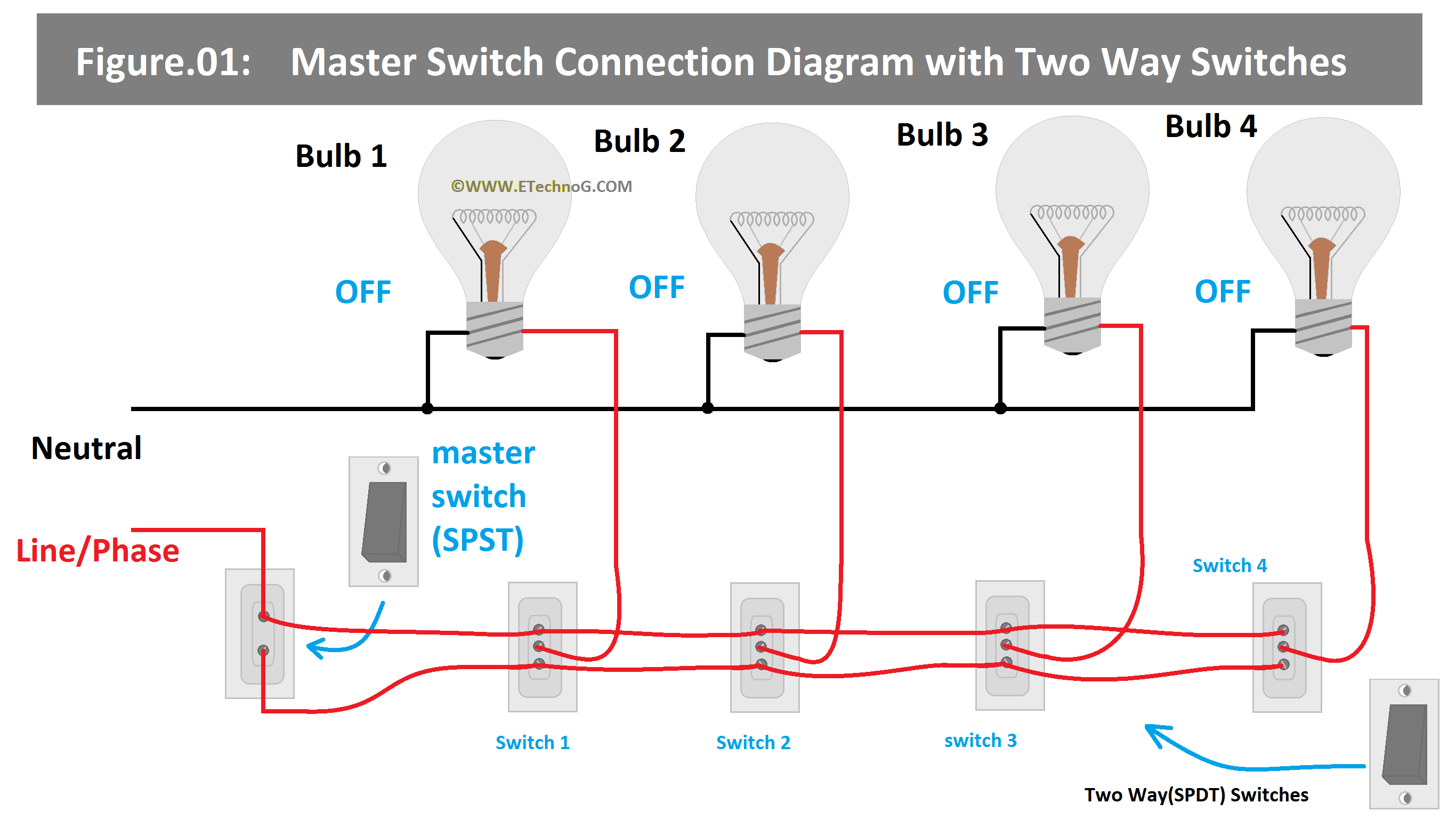
Here, we have given a wiring diagram to explain the connection of the master switch with two-way switches.
Wiring Procedure
As you see in the above diagram, here a one-way switch or SPST switch is used as the master switch. Remember that the master switch should have a higher current and voltage handling capacity than the two-way switches as it controls the whole power through it whereas two-way switches handle power to their respective loads only.
1. The neutral terminal of all the loads(here lights) is connected to the neutral terminal of the power source directly.
2. The phase or live terminal from the power source is connected to one terminal of the Master Switch and the upper terminals of all the two-way switches.
3. The other terminal of the master switch is connected to the lower terminals of all the two-way switches.
4. The middle terminal of each two-way switch is connected to the phase terminal of their respective loads(here room lights).
Working Principle
To understand the working principle, we can take an example of any one load. Here we use light as a load. For example, when the master switch is off and the first two-way switch in the first room can be operated to turn off and turn on the light.
When the master switch is off and the first switch is pressed in the down position bulb 1 will be in off condition because the bulb will get not any phase supply as the master switch is off. But when the switch is pressed at the up position the light will glow as it will get the phase supply.
Now when the master is turned on, the bulb cannot be turned off by operating the two-way switch because at every position it will get the phase supply. This same principle is applied to all the room lights.
Here are some conditions for operating all the bulbs as per the above diagram,
All Lights OFF
Master Switch - OFF
First Two-Way Switch - Down
SecondTwo-Way Switch - Down
Third Two-Way Switch - Down
Fourth Two-Way Switch - Down
Only Bulb 1 ON
Master Switch - OFF
First Two-Way Switch - Up
SecondTwo-Way Switch - Down
Third Two-Way Switch - Down
Fourth Two-Way Switch - Down
Only Bulb 2 ON
Master Switch - OFF
First Two-Way Switch - Down
SecondTwo-Way Switch - Up
Third Two-Way Switch - Down
Fourth Two-Way Switch - Down
Only Bulb 3 & 4 ON
Master Switch - OFF
First Two-Way Switch - Down
SecondTwo-Way Switch - Down
Third Two-Way Switch - Up
Fourth Two-Way Switch - Up
All Lights On(Even the Master Switch OFF)
Master Switch - OFF
First Two-Way Switch - Up
SecondTwo-Way Switch - Up
Third Two-Way Switch - Up
Fourth Two-Way Switch - Up
All Lights On
Master Switch - ON
In this case, Operating two-way switches cannot turn off lights.
Read Also:

