Intermediate Switch Wiring Diagram and Connection Procedure
In this article, we are going to see the wiring diagram and connection procedure for Intermediate Switch. An intermediate switch is a type of electrical switch commonly used in lighting circuits to control a single light fixture or a group of lights from multiple locations. It is often employed in scenarios where you have a light that can be turned on or off from three or more different switch locations, allowing you to control the light from any of those points.
In a standard lighting circuit, you have two-way switches, which are also known as single-pole double-throw (SPDT) switches. These switches allow you to control a light from two different locations, such as one switch at the top of the stairs and another at the bottom. However, if you want to control the same light from additional locations, you'll need an intermediate switch.
The intermediate switch is essentially a specialized three-way switch, also known as a double-pole double-throw (DPDT) switch. It has four terminal connections rather than the two found in a standard two-way switch. With an intermediate switch, you can extend the control of the light to as many locations as needed, with each intermediate switch connecting to the other two-way switches in the circuit.
Remember that the intermediate switch is known as a 3-way DPDT switch in the UK and IEC following countries. The intermediate switch is also known as the Crossover switch or 4-Way DPDT switch in North America, USA, and NEC following countries.
Wiring Diagram
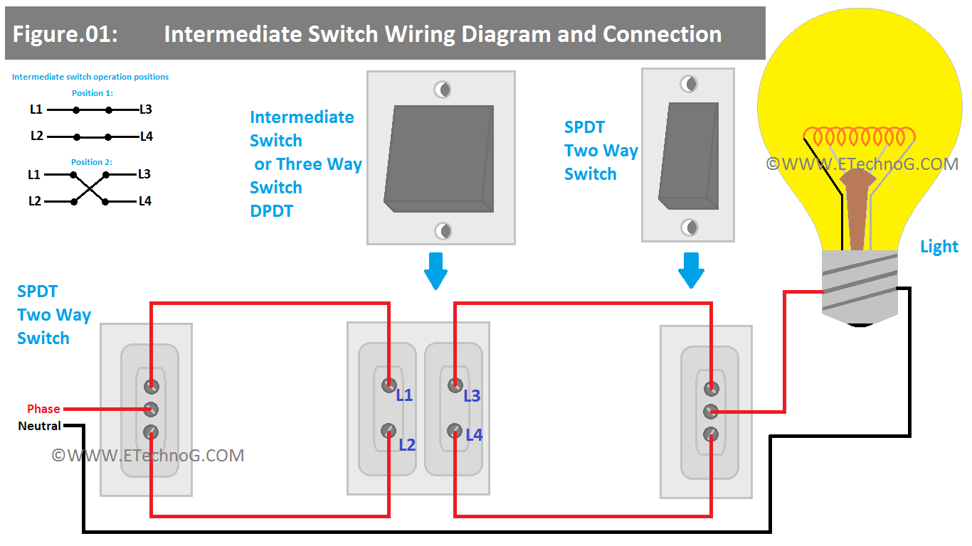
Here, you can see the Intermediate Switch Wiring Diagram and Connection with two-way switches.
Connection Procedure
The intermediate Switch is to be installed in the middle of two two-way switches.
1. Each two-way switch has three terminals - one common (COM) terminal and two other (L1 and L2) terminals. Connect the Phase or Line terminal of the power source (from your electrical panel or distribution board) to the common terminal of the first two-way switch.
2. Connect the L1 and L2 terminals of the first two-way switch to the L1 and L2 terminals of the intermediate switch.
3. Connect the L2 and L3 terminals of the intermediate switch to the L1 and L2 terminals of the second two-way switch that is installed after the intermediate switch.
4. Now Connect the common terminal of the second two-way switch to the phase terminal of the light.
5. Connect the neutral terminal of the light to the neutral terminal of the power source directly.
6. If you want to control the light from more places then add more intermediate switches. One new addition of an intermediate switch allows you to control the light from one more place. When you add an extra switch you have to connect the output of the first intermediate switch to the input of the new intermediate switch. Then the output of the new intermediate switch should be connected to the input of the last two-way switch.
Operation
1. Let's assume the light is in off condition.
2. If you operate the first two-way switch, the light will be turned ON.
3. After that if you operate the intermediate switch the light will be turned OFF.
4. After that if you operate the second two-way switch the light will be turned ON again.
5. If anyone again operates the first two-way switch, the light will be turned Off.
In summary, the intermediate switch (three-way switch) changes the path of the current between all three switches, thereby controlling the light from any of the three switch locations is possible.
Read Also:

