Hotel Bell Indicator Circuit Wiring Diagram and Connection
Hey, in this article, we are going to see the Hotel Bell Indicator Circuit Wiring Diagram, Its Connection Procedure, and Working Principle. The Hotel Bell Indicator Circuit is used in hotels to provide a visual indication with a calling sound or to aware the hotel staff when a guest presses the bell or calls for assistance from their room. This circuit is commonly installed in the reception area or other designated areas where hotel staff are present to attend to guest requests.
The Hotel Bell Indicator Circuit is a simple yet effective way to ensure that guests' needs are attended to quickly and efficiently, enhancing their overall experience during their stay at the hotel. It allows hotel staff to provide a high level of customer service and responsiveness, which is crucial for guest satisfaction and loyalty.
Wiring Diagram
Here you can see the wiring diagram of the Hotel Bell Indicator System. The push-button switches are installed in the guest rooms and the rest all the circuits are installed in the reception area.
Connection Description
1. Phase or Live wire from the power source is connected to one terminal of all the push button switches.
2. Another terminal of the switches is connected to the phase terminal of their respective lights.
3. The other terminal of all the lights is connected to the phase terminal of the calling bell.
4. Finally, the neutral terminal of the calling bell is connected to the neutral terminal of the power source.
Working Principle
When the guest presses the push button switch the circuit will complete through the light and the calling bell so the respective light will glow and the calling bell start ringing. For example, when the guest presses the switch in room 1 the lamp 1 will glow and the bell will ring.
Advanced Bell Indicator Circuit for Hotelling
The above normal switching method has a drawback which is when there is no person in reception and the guest presses the calling switch, the receptionist will not be aware when he comes back to the reception. This is because when the guest presses the switch that time only the light will glow and the bell ring.
To overcome this problem we need an arrangement that will keep glowing the indication light until the receptionist turned it off manually.
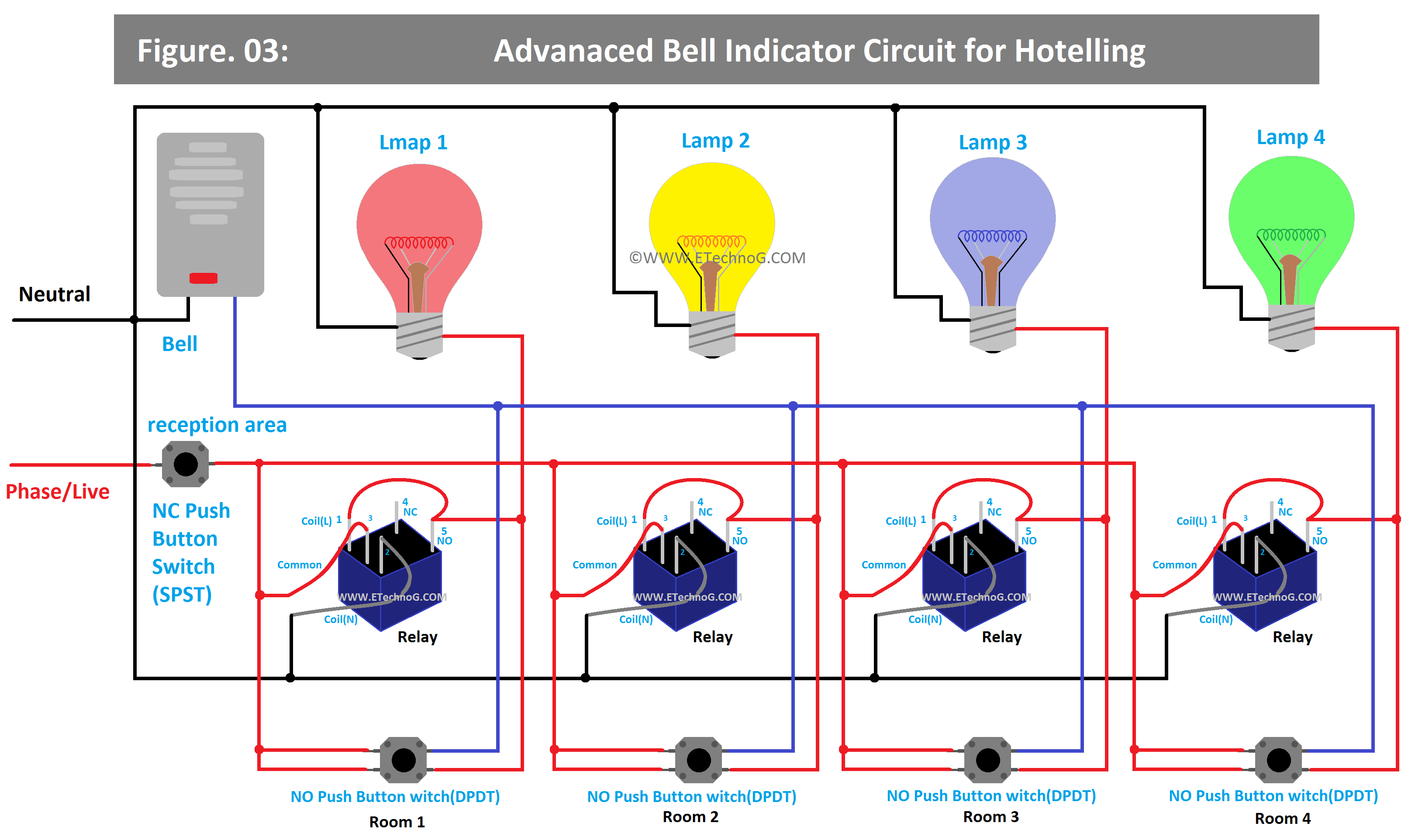
Here is the wiring diagram,
As you see in the above wiring diagram, the circuits include relays and a push-button switch for reception.
The push button switch or calling switch installed in the guest rooms are the Normally Open(NO) Switches and the push button switch installed in the reception is a Normally Closed(NC) switch.
When the guest press the calling switch from their room the respective indication light will glow in the reception. The calling bell will ring as per its set time duration but the indication will glow until the receptionist press the NC push button switch.
So when the receptionist is not present in the reception but the guest calls, the receptionist will be aware after coming back to the reception as the indication light is still glowing.
Read Also:
- Hallway or Corridor Lighting Wiring Diagram and Connection
- Staircase Wiring Diagram(Control Light from 2 or More Places)
- Hospital Lighting Circuit Wiring Diagram and Connection
- Hostel Lighting System Wiring Diagram and Connection Procedure
- Tunnel Light Wiring Diagram and Connection Procedure
- Warehouse/Godown Light Wiring Diagram and Connection Procedure


