Exhaust fan Connection Diagram with Switch, Timer, GFCI
Here, in this article, we are going to see the Exhaust fan Connection Diagram in different arrangements such as connection with an SPST Switch, Timer, GFCI Combo Switch, etc.
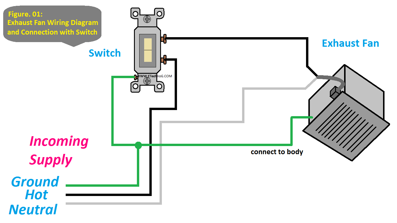
Exhaust fan Connection Diagram with a Switch
Connecting an exhaust fan with a switch is a straightforward electrical wiring task. The purpose of the switch is to control the power supply to the exhaust fan, allowing you to turn it on or off as needed. In the power source junction box, you will typically have a Live wire (Line) and a Neutral wire (Common). The Live wire carries the current from the power source, while the Neutral wire completes the circuit.
1. Connect the Live or Hot wire(here Black color) from the power source to one terminal of the switch. This is typically the terminal labeled "L" or "COM" (common).
2. Then, connect another wire from the other terminal of the switch, usually labeled "1" or "A" (for single-pole switches), to the Live wire going to the exhaust fan.
3. Connect the Neutral wire(here white color) from the power source directly to the Neutral wire of the exhaust fan.
4. Connect the ground wire(green or bare copper) to the metal body of the exhaust fan.
Exhaust fan Connection Diagram with a Timer
1. Connect the white wire(neutral) from the exhaust fan to the white wire from the power source.
2. Connect the black wire(hot) from the power source to the "Line" terminal(black) of the timer.
3. Connect the black wire from the exhaust fan to the "Load" terminal(red) of the timer.
4. Connect the ground wire(green or bare copper) to the metal body of the exhaust fan.
Read Also: GFCI Outlet Wiring and Connection Diagram
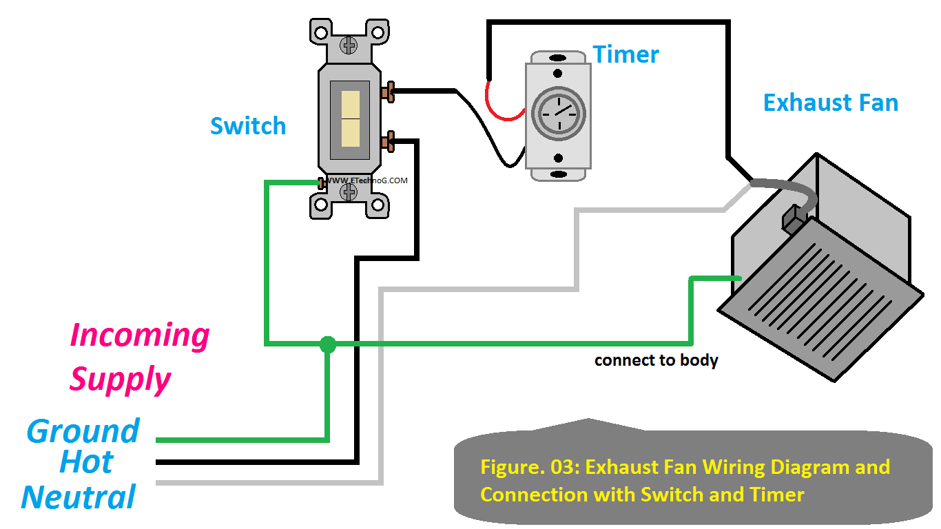
Exhaust fan Connection Diagram with a Switch and a Timer
1. Connect the black wire(hot) from the power source to the "Line" terminal(black) of the Switch.
2. Connect the black wire(hot) from the Load Terminal of the Switch to the "Line" terminal(black) of the timer.
3. Connect the black wire from the exhaust fan to the "Load" terminal(red) of the timer.
4. Connect the Neutral wire(here white color) from the power source directly to the Neutral wire of the exhaust fan.
5. Connect the ground wire(green or bare copper) to the metal body of the exhaust fan.
Exhaust fan Connection Diagram with a GFCI Combo Switch
1. Connect the black wire(hot) from the power source to the "Line" terminal on the GFCI combo switch.
2. Connect the "Load" terminal(Hot) of the GFCI combo switch to any one terminal of the switch controller using a short black wire.
3. Connect the black wire from the exhaust fan to another terminal of the switch controller.
4. Connect the white wire(neutral) from the power source to the "Neutral" terminal on the GFCI combo switch.
5. Connect the white wire from the exhaust fan to the "Load" terminal(Neutral) of the GFCI combo switch.
6. Connect the ground wire(green or bare copper) to the ground terminal of the GFCI combo switch and the metal body of the exhaust fan.
Exhaust fan Connection Diagram with a GFCI Combo Switch and a Timer
1. Connect the black wire(hot) from the power source to the "Line" terminal on the GFCI combo switch.
2. Connect the "Load" terminal(Hot) of the GFCI combo switch to any one terminal of the switch controller using a short black wire.
3. Connect the other terminal of the Switch controller to the "Line" terminal(black) of the timer.
4. Connect the black wire from the exhaust fan to the "Load" terminal(red) of the timer.
5. Connect the white wire(neutral) from the power source to the "Neutral" terminal on the GFCI combo switch.
6. Connect the white wire from the exhaust fan to the "Load" terminal(Neutral) of the GFCI combo switch.
7. Connect the ground wire(green or bare copper) to the ground terminal of the GFCI combo switch and the metal body of the exhaust fan.


