XLR Pinout, Wiring Diagram - Male and Female Connector
XLR Connector is an electrical connector used for the audio signal, video signal, and electrical power transmission. In a professional audio system, you can see most of the applications. This type of connector is heavier than others and circular in size. They are used for different types of audio devices such as mixers, equalizers, amplifiers, microphones, etc. Nowadays you can see its applications in lighting systems such as stage lighting. For smart lighting systems, it helps a lot. The main advantage of the XLR connector is that it can carry balanced signals which reduces noise and interference, especially over long cable runs.
XLR Connectors are available in both Male and Female connectors. There are various types of XLR connectors available according to the pin numbers, part numbers, construction, etc. In this article, we are going to see three-pin, five-pin, and seven-pin connector diagrams. Among those, the three-pin connectors are used for a balanced audio system, in fact, it is mostly used.
When using a condenser microphone, it requires an auxiliary power supply for its operation. So, a DC power(generally 48V DC) is provided through two lines to the microphone. This power is known as phantom power. These microphones are connected to the system by using the balanced audio connector or 3 pins XLR Connector.
3 Pin XLR Pinout Diagram - Male and Female Connector
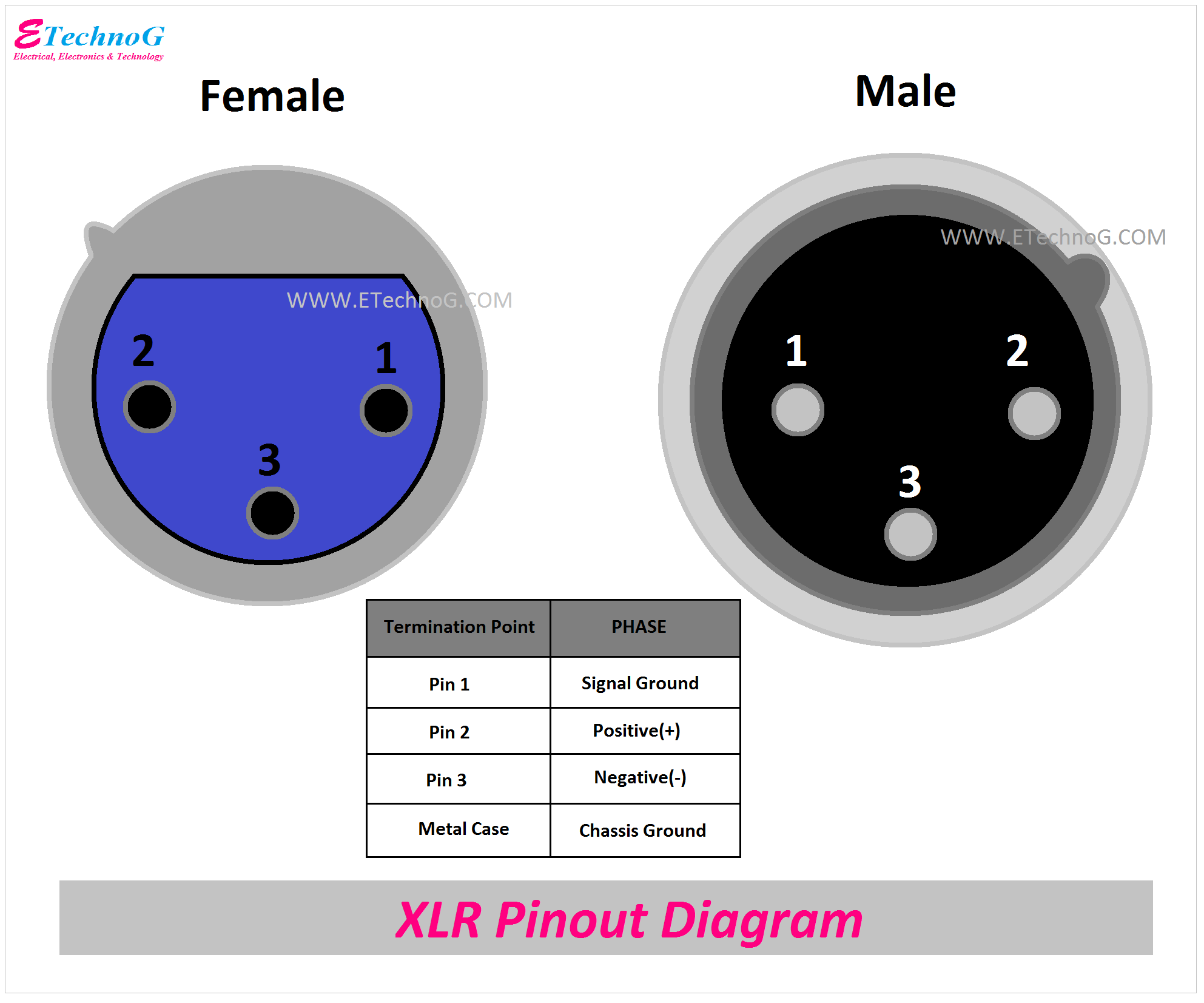
Here, you can see the pinout diagram of three-pin XLR Connector.
Pin 2 is used for positive signal or high signal whereas pin 3 is used for negative signal or low signal. Pin 1 is used for system ground. The metallic case of the connector is also connected to the ground. And it is known as chassis ground so the pin 1 and metal case are connected together.
XLR Connector Wiring and Connection Diagram
Here, you can see the wiring and connection between a male connector and a female connector.
Generally, pin 2 or positive pins are connected with a red wire, pin 3 or negative pins are connected with a black wire, and pin 1 or ground pins are connected through a shielded wire.
5 Pin XLR Connector Pinout Diagram - Male and Female
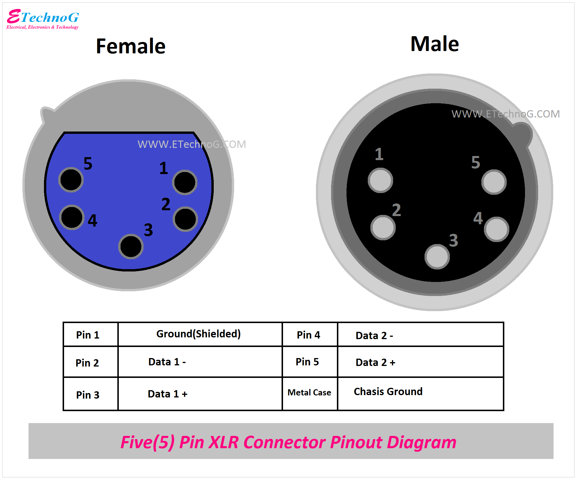
Here, you can see the pinout diagram of the 5-pin XLR Connector.
Here, the pins are,
Pin 1 - Common Grounded
Pin 2 - Data 1 -
Pin 3 - Data 1 +
Pin 4 - Data 2 -
Pin 5 - Data 2 +
Metal Case - Chasis Ground
Actually, these pin functions depend on the applications or where it is used. In some connectors when used for connecting the condenser type microphone, pin 1 is connected to the chassis ground, pin 2 is used for power ground, Pin 3 is used for positive voltage(+15V or +16V), Pin 4 is used for negative Voltage(-15V or -16V), and pin 5 is used for phantom power voltage 48V.
7 Pin XLR Connector Pinout Diagram - Male and Female
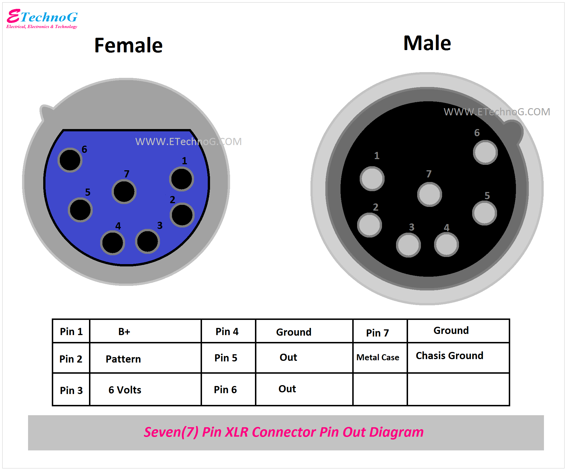
Here, you can see the pinout diagram of the 7-pin XLR Connector Pinout Diagram.
These connectors are used for complex circuits such as broadcast studios, analog lighting control systems, etc where more connections or data lines are required.
Read Also:


