RS 232 Pinout, DB9 Pinout, RS 485 Pinout Diagram Explained
RS 232 is a standard for serial communication of transmission data. The signals connecting between Data Terminal Equipment(DTE) and Data Communication Equipment(DCE) can be defined as the RS 232. An example of Data Terminal equipment is a computer. On the other hand, an example of data communication equipment is a modem.
The RS 232 defines the electrical characteristics of the signal, the timing of signals, and the physical size and pinout of the connector. RS 485 is also a standard for serial communication. These RS 232 and RS 485 connectors are referred to as DB9 connectors because they have 9 pins or data lines. The RS-485 is also known as TIA-485(-A) or EIA-485. RS 232 is mostly used in local computer appliances whereas the RS 485 is used in industrial control circuits and systems.
RS232 is used for short-distance, one-to-one communication (like between a computer and a device) and works with 3 wires. It is less resistant to noise and supports distances up to 15 meters. On the other hand, RS485 is designed for long-distance communication (up to 1,200 meters) and can connect multiple devices using just 2 wires.
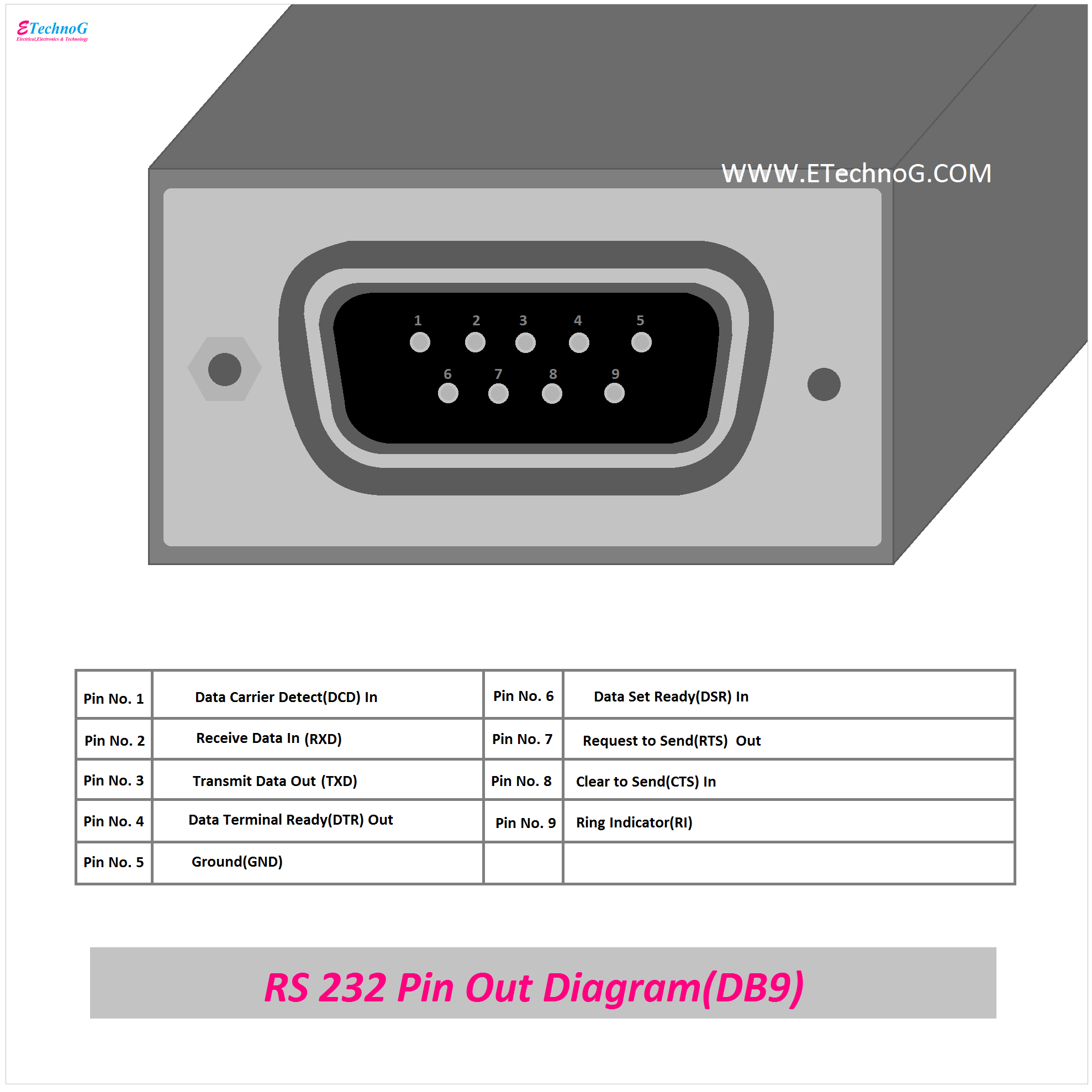
RS 232 Pinout Diagram(DB9)
Here, you can see the pinout diagram of RS 232(DB9 Connector)
Here, you can see a total of nine(9) lines or ports. From the upper left side, it is to be counted from number 1. It is a DB9 Male connector. For a female connector, the upper right side to the left is to be counted from number 1. Here are the pin details,
Pin No. 1 - Data Carrier Detect(DCD) - In
Pin No. 2 - Received Data(RXD) - In
Pin No. 3 - Transmit Data(TXD) - Out
Pin No. 4 - Data Terminal Ready(DTR) - Out
Pin No. 5 - Ground(GND)
Pin No. 6 - Data Set Ready(DSR) - In
Pin No. 7 - Request to Send(RTS) - Out
Pin No. 8 - Clear to Send(CTS) - In
Pin No. 9 - Ring Indicator(RI)
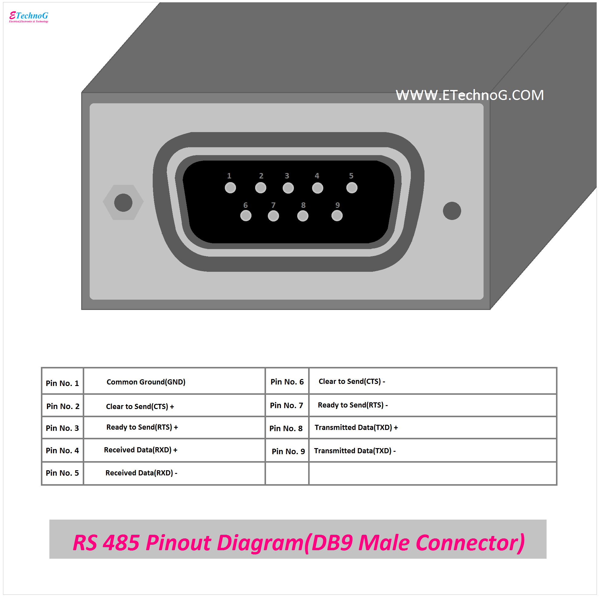
RS 485 Pinout Diagram(DB9 Male Connector)
Here, you can see the pinout diagram of RS 485(DB9 Male Connector)
RS 485 can be used with local networks and it can be used up to 10 Mbit/s. Generally, the RS 485 drivers use three-state logic that allows deactivating the transmitters individually. In most of the cases, the RS 485 only specifies the electrical characteristics or it works with only the physical layer but it does not specify any communication protocol. The RS 485 is also widely used in the automation system for data saving, data storing, controlling, etc.
Here are the pin details,
Pin No. 1 - Common Ground(GND)
Pin No. 2 - Clear to Send(CTS) +
Pin No. 3 - Ready to Send(RTS) +
Pin No. 4 - Received Data(RXD) +
Pin No. 5 - Received Data(RXD) -
Pin No. 6 - Clear to Send(CTS) -
Pin No. 7 - Ready to Send(RTS) -
Pin No. 8 - Transmitted Data(TXD) +
Pin No. 9 - Transmitted Data(TXD) -
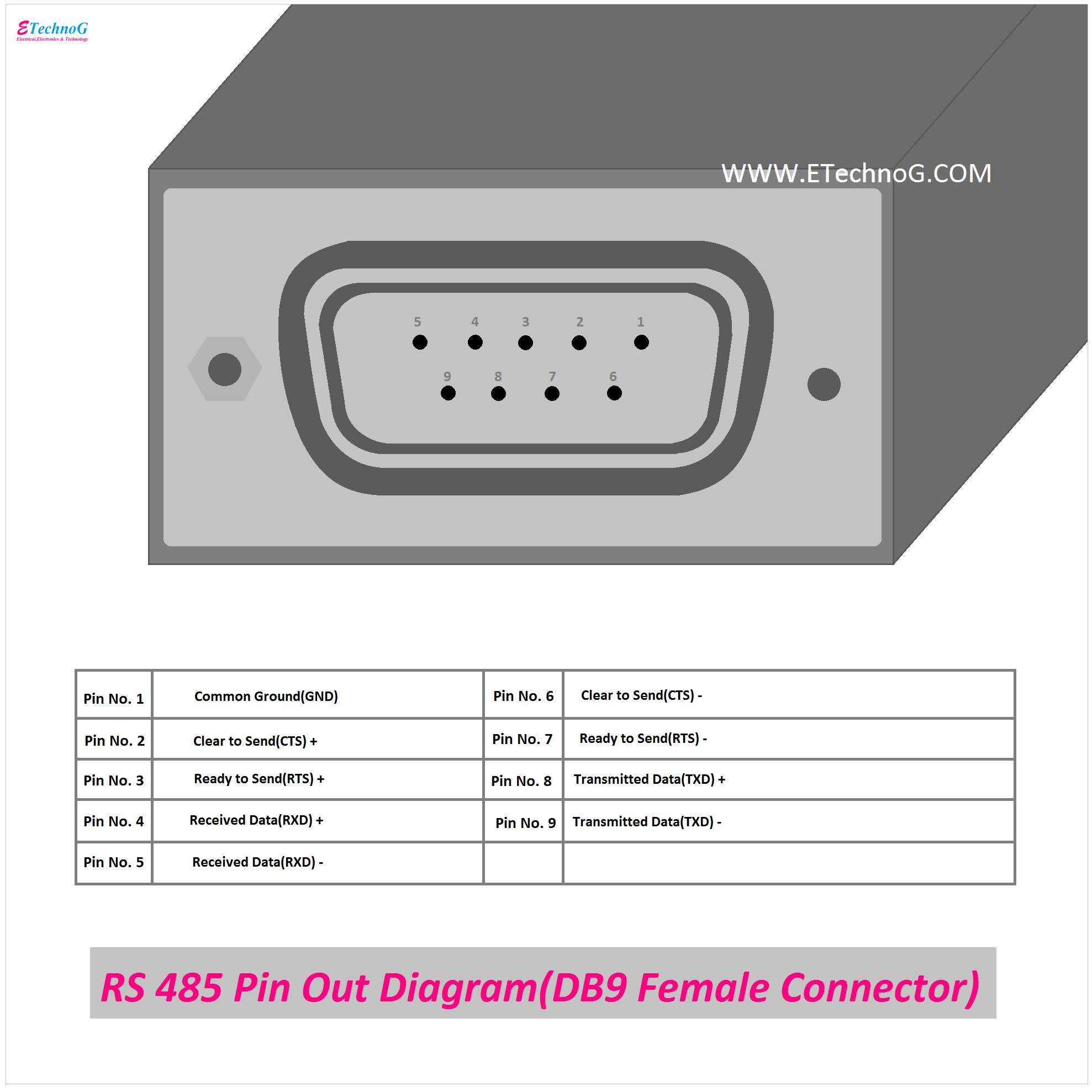
RS 485 Pinout Diagram(DB9 Female Connector)
Here, you can see the Pinout Diagram of RS 485 Pinout Diagram(DB9 Female Connector)
For the male connector, the pins should be counted from the upper left port, but in the case of the female connector, the ports should be counted from the upper right port.
Here are the Pin Details,
Pin No. 1 - Common Ground(GND)
Pin No. 2 - Clear to Send(CTS) +
Pin No. 3 - Ready to Send(RTS) +
Pin No. 4 - Received Data(RXD) +
Pin No. 5 - Received Data(RXD) -
Pin No. 6 - Clear to Send(CTS) -
Pin No. 7 - Ready to Send(RTS) -
Pin No. 8 - Transmitted Data(TXD) +
Pin No. 9 - Transmitted Data(TXD) -
Read Also:


