What is Relay Switch? Circuit Diagram and Working Principle
The electronic switch built with relays is called relay switch. Basically, it is an electronic circuit built with relays, transistors, diodes, resistors. An individual relay can be used as a switch but it will not perform efficiently for the electronic signal or pulse signal. To make the relay more sensitive and high efficient some active and passive components are connected with it which can be called a relay switch. In an electrical circuit, a single relay can give the desired output because there high-speed switching is not required but in an electronic a single electromechanical relay can operate with high speed. So to obtain the high-speed switching from an electromechanical relay we need to design an electronic relay switch circuit.
Relay Switch Circuit Diagram
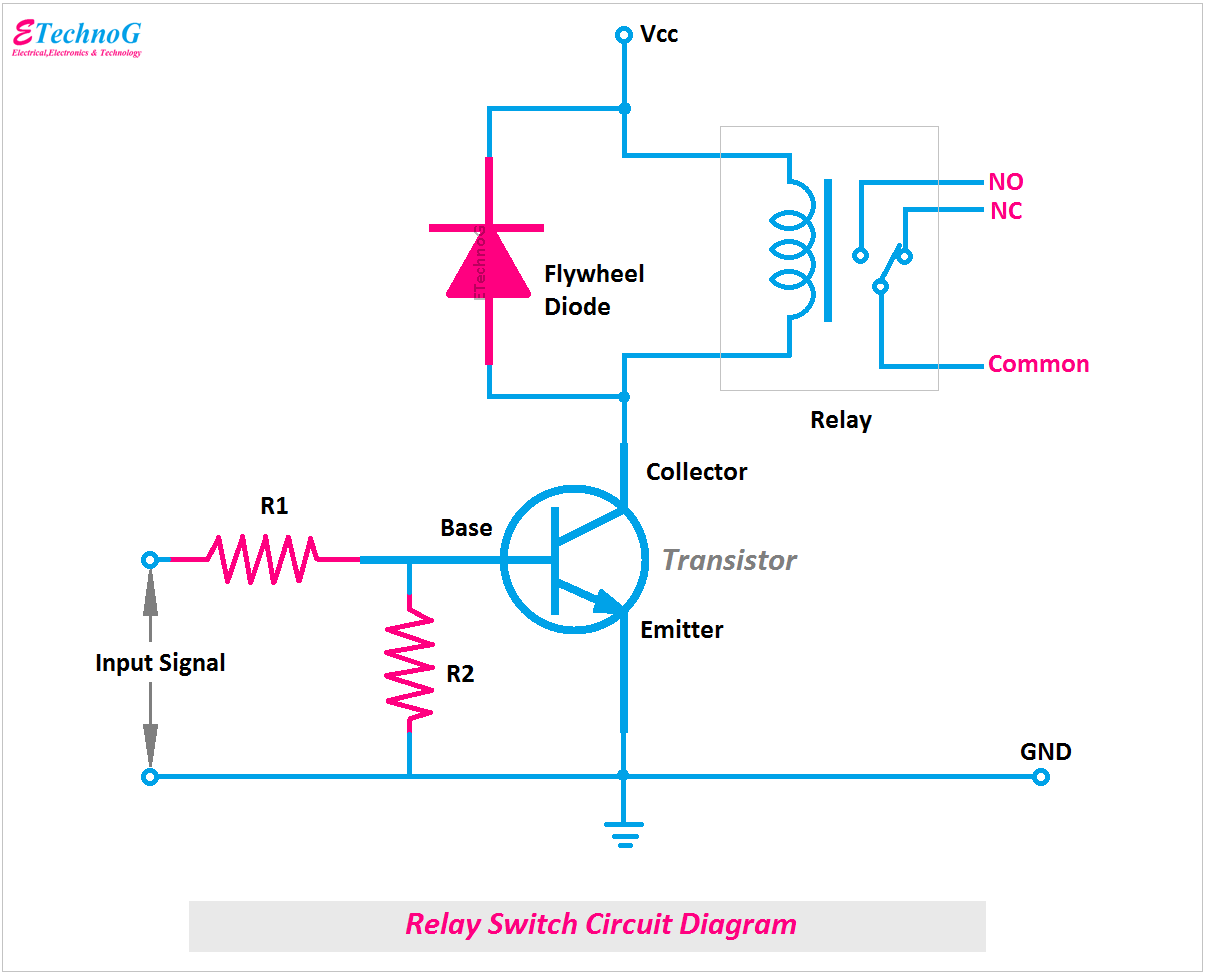
First of all, let's see the circuit diagram of relay switch to understand its working principle.
You can see the coil of the relay is connected in series with the collector terminal of the NPN transistor. We know that when there is no voltage at the base terminal of the transistor, it will act as an open circuit. So, this time no current will flow through the relay coil as it not getting any closed path. But when a positive voltage is applied(more than threshold voltage) to the base terminal, the transistor will act as a short circuit. In this time, an electric current will flow through the relay coil as it got a closed path through the transistor. So, the relay will actuated. The NO terminal become NC and NC terminal become NO.
Working Principle of Relay Switch
Now, the question is how the relay operates. The relay will operate when its coil gets the voltage or current. We know the transistor is connected in series between the relay coil and the supply terminals. So when it makes the closed-circuit the relay coil will get the supply voltage from the main power supply and it will operate.
Now, the condition 1, there is no voltage across the base terminal of the transistor. So the transistor will act as an open circuit. So the relay coil will not get any power supply hence it will not operate.
Now, the condition 2, a voltage is applied to the base terminal of the transistor. So the transistor will act as a closed circuit. The relay coil will come across the full supply voltage. Now the relay will operate to change its NC terminal into NO and NO terminal into NC. So, the signal will be Switched through the relay.
The function of Flywheel Diode in the Relay Switch Circuit
You can see in the above circuit diagram, a flywheel diode is connected across the relay coil. It is nothing but a PN junction diode is connected in reverse bias parallel to the relay coil. The main function of this diode is to circulate the feedback current generating from the relay coil and to oppose to flow to the control circuit. When the switching function happens, the relay coil generates a feedback current opposite direction to the main current due to its self-inductance property. If this feedback current flows towards the control circuit a disturbance will happen. So to prevent this problem a PN junction diode known as freewheeling diode or flywheel diode is connected across the relay coil.
Relay Switch Function
- It switches the electrical or electronic signal
- It provides high-speed switching
- It increases the efficiency of an electromechanical relay
- It makes ready the electromechanical relay to operate with pulse signals
- Contact less operating.
- Isolation between controlling and controlled circuit.
Relay Switch Applications
1. Relay switch used for motor controls with microcontrollers or other programming devices.
2. Relay switch used in light dimmer circuits.
3. Relay switch used in electronic control circuits.
4. Relay Switches are used in automation systems.
Read Also:
What is Relay Switch? Circuit Diagram and Working Principle
 Reviewed by Author
on
December 11, 2021
Rating:
 Reviewed by Author
on
December 11, 2021
Rating:

