Limit Switch Wiring Diagram and Connection Procedure
The limit switch is an electromechanical switch that is operated by the motion of a machine or any physical force. Limit switches are used in automatic motor direction control, door interlocking systems, machinery control, safety interlock systems, etc.
There are four types of limit switches available in the market such as Whisker type limit switch, roller type limit switch, lever type limit switch, and plunger type limit switch. These are used for different applications. They all provide the electrically same function, just the operating system is different. In this article, we are going to see the wiring diagram of a micro lever-type limit switch that is mostly used in electrical circuits, electronic devices, door controllers, etc.
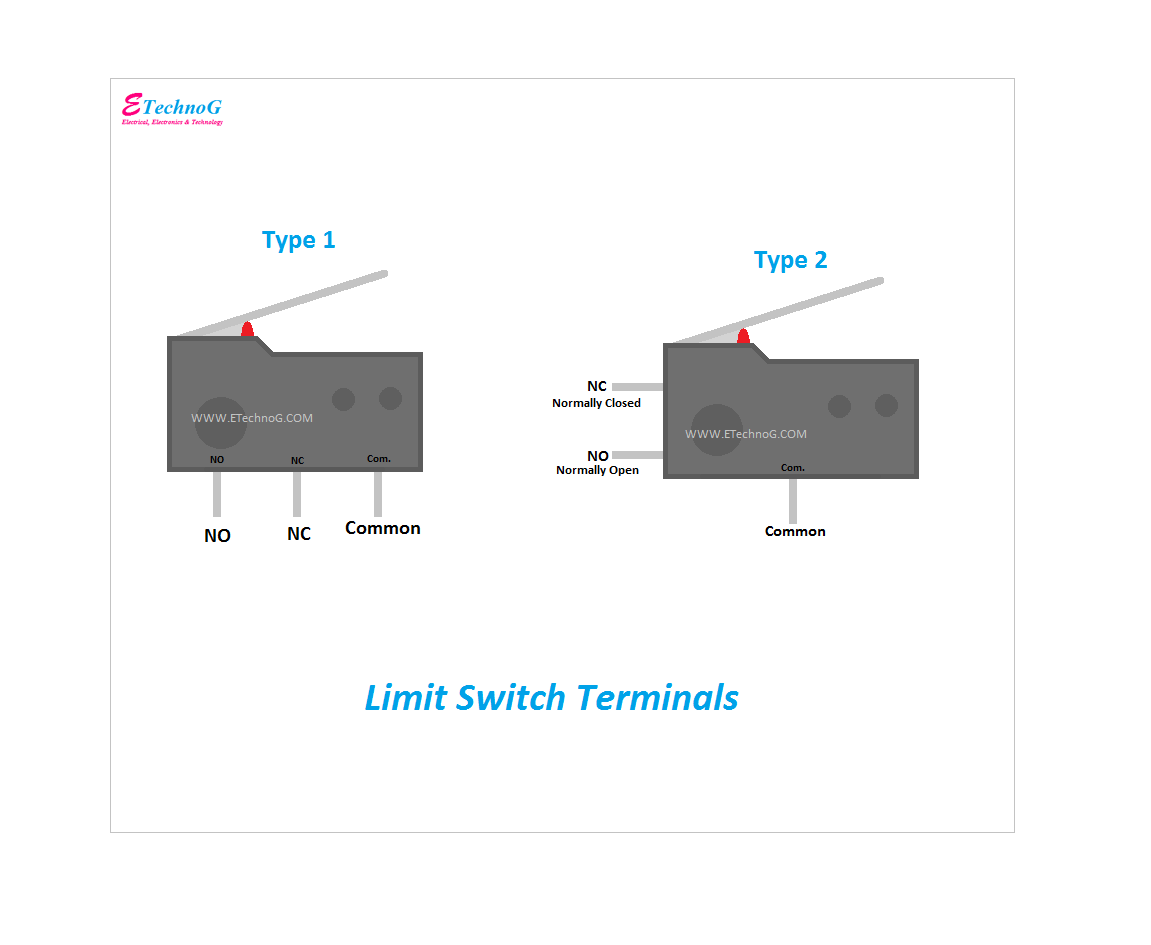
Limit Switch Terminals
Here, you can see the terminals of an SPDT or Single Pole Double Throw Limit Switch. Based on the terminal brought outside, there are two types of limit switches available.
You can see the SPDT limit switch has a total of three terminals - Common, Normally Closed(NC), and Normally Open(NO). When the lever of the switch is not pressed the NC terminal is connected to the common terminal but when the lever of the switch is pressed the NC terminal is disconnected from the common terminal and the NO terminal will connect to the common terminal. Now we will understand the working principle from the connection diagram.
Limit Switch Wiring Diagram
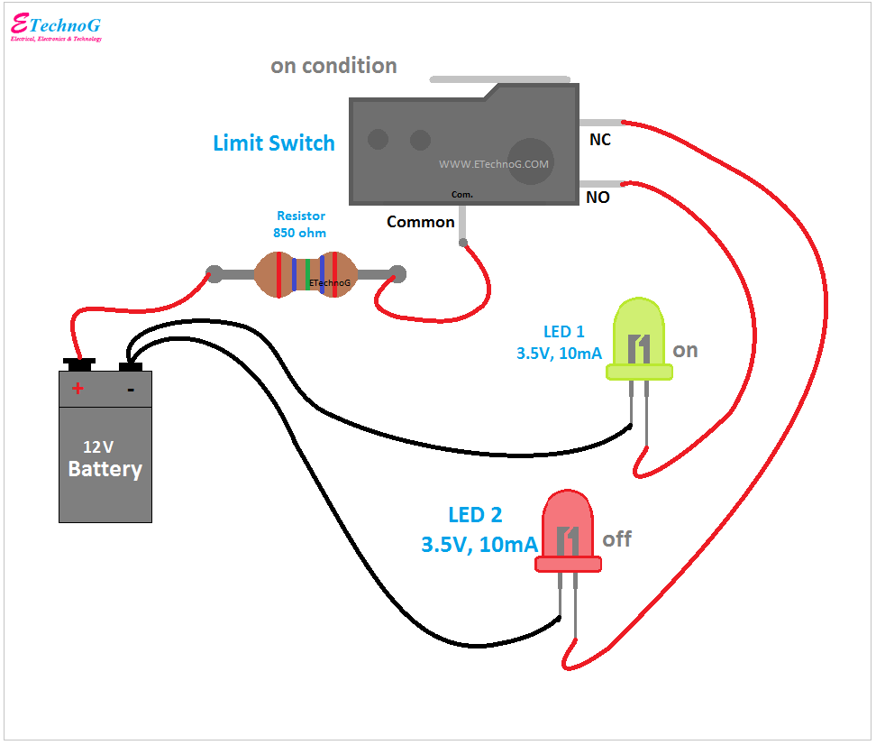
Here, you can see the wiring of limit switch.
To understand its working principle we have connected two LEDs with a battery. Here, we have used a 12V battery, a Green Color LED(3.5V,10mA), and a Red Color LED(3.5V, 10mA). We can not connect the 3.5V LED directly to the 12V battery. So we have used a resistor of 850 ohms.
Connection Procedure
1. Connect the positive terminal of the battery to the common terminal of the limit switch through an 850 Ohms series resistor.
2. Connect the negative terminal of both LEDs to the negative terminal of the battery.
3. Connect the positive terminal of the green color LED to the NO terminal of the limit switch.
4. Connect the positive terminal of the red color LED to the NC terminal of the limit switch.
Working Principle
Now, let's see how the circuit works.
Condition 1: Limit Switch is in OFF Condition
When the limit switch is in OFF condition, the NC terminal is connected to the common terminal, and the NO terminal is disconnected from the common terminal. So the red color LED will get the power supply and it will glow while the green color LED will be in the off condition.
Condition 2: Limit Switch is in ON Condition
When the limit switch is in ON condition, the NO terminal will be connected to the common terminal and the NC terminal will be disconnected from the common terminal. So, the green color LED will get the power supply and it will glow while the red color LED will be in the off condition.
Read Also:


