Connector OBD2 Pinout Diagram | On Board Diagnostics
OBD or On-Board Diagnostics is a diagnosis system consisting of a computer-based application used in cars, that monitors and handles measurement-related works for the car speed, mileage, fuel consumption, etc. It is only the device that helps us to see all the data in a display(may be analog or digital). It also works as the engine control unit or ECU that measures some vital parameters of the Engine. Basically, it works as an interface between physical devices or sensors and programming devices. This diagnosis helps to monitor or take care of the health of the car. The warning lights, display, or car dashboard are also controlled by this OBD system.
You can see the OBD2 port near the driver dashboard. It is a 16-pin connector or port. Any mechanic or technician easily can find out the error code by connecting a special scan tool to this port. The code of the OBD port by manufacturer to manufacturer but using a special scan tool it is easy to read the actual code. Some ports of this OBD2 Connector use standard numbers and positions for all the manufacturers. This standard port position helps to connect the scan tool easily.
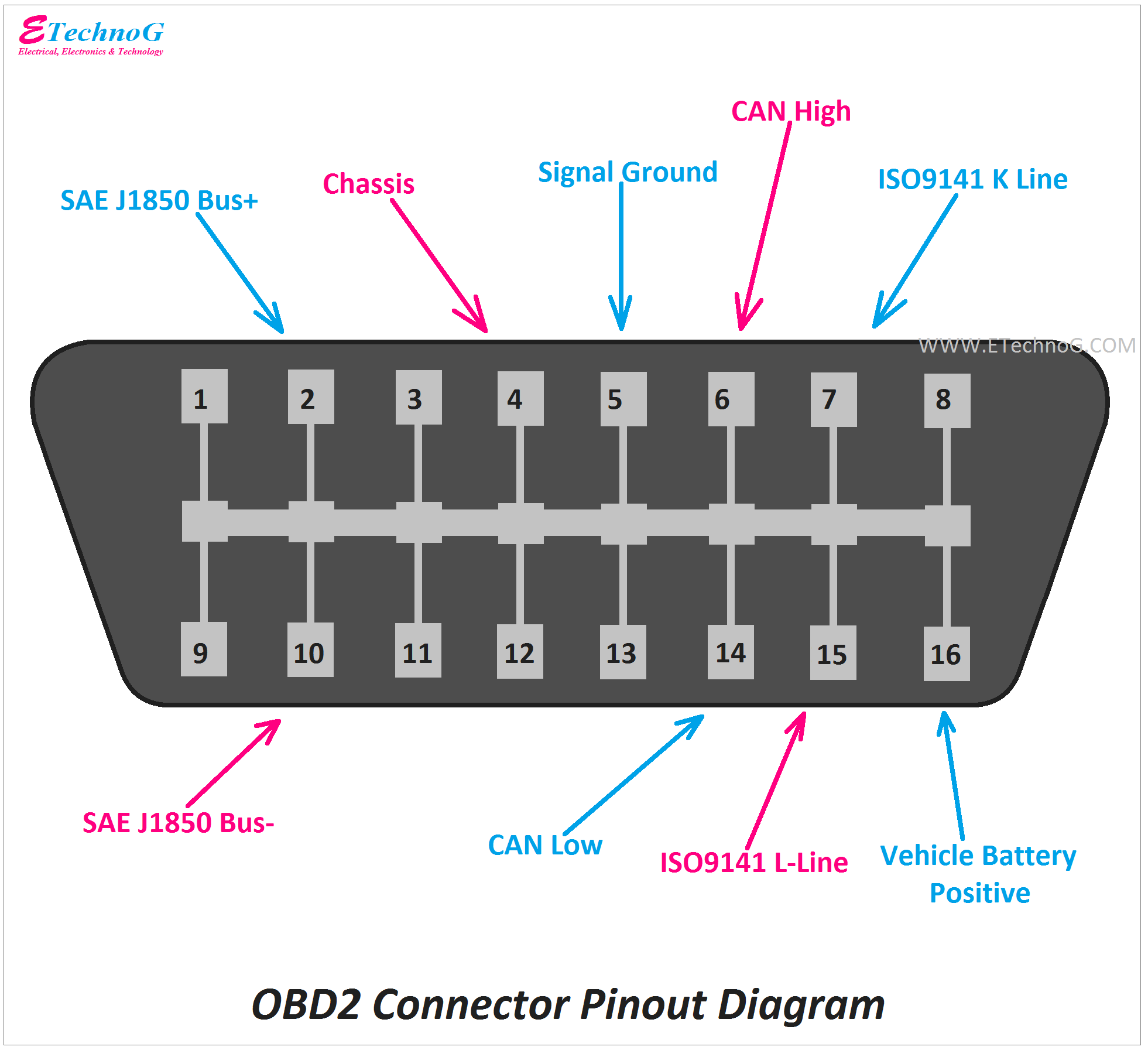
Here, You can see the pinout diagram of OBD2 connector.
Pin Details are here,
Pin No. 1 - This pin is not standard. The function of this pin is depend upon the manufacturer. For different versions, it may have different functions.
Pin No. 2 - This pin is named as "SAE J1850 Bus+". This is the bus-positive pin of the protocol. It is used by GM vehicles. This protocol uses PWM(Pulse Width Modulation) and VPW or Variable Pulse Width.
Pin No. 3 - This pin is not standard. The function of this pin is depend upon the manufacturer.
Pin No. 4 - Connected to Chassis Ground or Negative
Pin No. 5 - Connected to Serial Ground
Pin No. 6 - This pin is named as "CAN High". It is the high pin of the CAN protocol(ISO15765-4). It provides 1Mbps speed with a 2-wire system.
Pin No. 7 - This pin follows the asynchronous serial communication protocol ISO9141. This pin is for K-Line.
Pin No. 8 - This pin is not standard. The function of this pin is depend upon the manufacturer.
Pin No. 9 - This pin is not standard. The function of this pin is depend upon the manufacturer.
Pin No. 10 - This pin is named as "SAE J1850 Bus-". This is the bus-positive pin of the protocol. It is also used by GM vehicles. This protocol uses PWM(Pulse Width Modulation) and VPW or Variable Pulse Width.
Pin No. 11 - This pin is not standard. The function of this pin is depend upon the manufacturer.
Pin No. 12 - This pin is not standard. The function of this pin is depend upon the manufacturer.
Pin No. 13 - This pin is not standard. The function of this pin is depend upon the manufacturer.
Pin No. 14 - This pin is named as "CAN Low". It is the low pin of the CAN protocol(ISO15765-4). It provides 1Mbps speed with a 2-wire system.
Pin No. 15 - This pin follows the asynchronous serial communication protocol ISO9141. This pin is for L Line.
Pin No. 16 - It is connected to the positive of the car battery.
Read Also:
- ATX Power Supply Pinout Diagram and Connector (20, 24 Pin)
- 4-Pin, 5-Pin Automotive Relay Pinout and Wiring Diagram
- How Vehicle Control Unit(VCU) Works? Learn with Block Diagram
- Car Sound System Wiring Diagram(Speaker, Amplifier, Receiver)
- Trailer Wiring Diagram - 4, 5, 6, 7 Pin/Wire (with Brakes, Lights)

