Wattmeter Connection Diagram and Wiring Explained
In this article, we are going to see the Wattmeter Connection Diagram and Wiring. Here we will see how to connect a wattmeter with a load and a power supply. The wattmeter is electrical measuring equipment that helps to measure the electrical power in the unit of Watt or Killo Watt or Mega Watt. Generally, a wattmeter has two coils - Current coils and pressure or voltage coils. Using the current coil measures the flow of electric current, and using the pressure or voltage coil it measures the supply voltage. By combining the voltage and current, it measures the electrical power. So first, let's see the internal circuit of the wattmeter, it will help to make the connection of wattmeter.
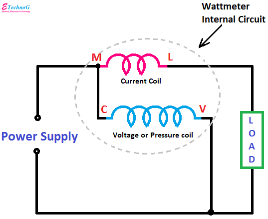
Wattmeter Internal Circuit
As you see in the above figure, the water meter has two coils - a current coil and a voltage or pressure coil. The current coil should be connected in the series with the load and the voltage or pressure coil should be connected across the power supply or load.
The two terminals of the current coil are denoted by M and L. The M terminal is to be connected to the power supply and the L terminal is to be connected to the Load. The two terminals of the voltage or pressure coil are denoted by C and V. The terminal C is to be connected to the phase and the V terminal is to be connected to the neutral.
Some characteristics of the current coil in wattmeter are,
1. It has fewer turns than a pressure coil
2. It has very low resistance
3. It allows the full load current to flow through it.
4. It causes copper losses.
Some characteristics of the pressure or voltage coil in the wattmeter are,
1. It has more turns than the current coil
2. It has high resistance
3. It allows very few current to flow through it, almost no current
4. As it conducts a very low current, so no copper loss happens
Wattmeter Connection Diagram
If your wattmeter has four terminals and they are marked by 1,2,3,4 then the following connection diagram should be followed.
In this wattmeter, terminals 1 and 2 for the voltage or pressure coil, and terminals 3, and 4 for the current coil. So first make a short between terminals 1 and 3. Then connect the phase to terminal 1 and neutral to terminal 2. Now the power supply connection is completed. Connect the phase terminal of the load to terminal 4 and connect the neutral of the load to terminal 2. Here, in the above figure, we have taken a bulb as a load.
Now, if your wattmeter has four terminals and is identified as M, L, C, and V then the following connection diagram should be followed.
As you see in the above connection diagram, first make a short between the M and C terminals. Connect phase to terminal M and neutral to terminal V. Connect the phase of the load to terminal L and neutral of the load to terminal V.
Read Also:


