Electrical Switch Board Connection Diagram and Wiring
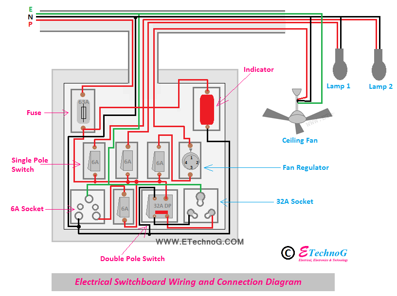
Hey, in this article you are going to learn how to wire a switchboard. Here, I have explained the electrical switchboard connection having a Fuse, Switches, Sockets, Indicator, and Fan Regulator. Also here, I have shown how to connect the switchboard with Lights and a fan for a room. This article will help you to make the connection of the switchboard at home very easily. You will see here that all are marked with a proper current rating that will help you very much in selecting the rating of switch, fuse, and sockets.
Electrical Switch Board Connection Diagram
In the above figure, you can see the electrical switchboard connection diagram has these following components-
1. 63 A Fuse(1 PCs)
2. 230V Indicator (1 PCs)
3. Single Pole(SP) Switch(4 PCs)
4. 32A Double Pole(DP) Switch(1PCs)
5. 230V Electronic Fan Regulator(1 PCs)
6. 6A socket(1 PCs)
7. 32A socket(1 PCs)
Read Also:
- Wiring Diagram for House with MCB Rating Selection Guide
- Wiring Diagram of Solar Panel with Battery, Inverter, Charge controller and Loads.
- Inverter connection diagram. Install Inverter and Battery at Home.
- [Explained] Connection of Tube Light with Diagram
- [Proper] Ceiling Fan Connection with Regulator, Switch and Capacitor
How to do Switch Board Connection
You can easily make the connection by observing the above diagram properly. I am going to tell a step-by-step procedure to do the connection the same as the above diagram.
1. Connect the phase of the main incoming power supply to any terminal of the fuse.
2. Connect any one terminal of each switch (SP, DP) together then connect to the fuse.
3. Connect the neutral to all sockets.
4. Connect the output of the DP switch to the 32A socket.
5. Connect the indicator just after the fuse as shown in the above figure and give neutral by taking a loop from any neutral point of the socket.
6. Connect the Ground wire to the ground terminal of each socket.
7. Connect the ceiling fan through the electronic regulator as shown in the above figure.
8. Connect the lamps as shown in the above figure.
Components Used to Make the SwitchBoard
1. Fuse
In the above wiring diagram, we have connected a 63A fuse in series with the main input phase supply. In this diagram, the total load of the circuit is 56A(calculated by the total of all switch ratings). So 63A is enough for this switchboard. But don't use the fuse having a current rating of less than 56A.
2. Switch
Here we have used two types of switches. Four PC 6A switches and one PC 32A switch. 32A switch is used for the 32A socket which can be used to connect any high-current equipment such as Mixers, heaters, Induction cookers, etc. 6A switch is enough for lights, fans, and low-power 6A sockets that can be used for mobile chargers, TVs, DVDs, etc connecting purposes.
3. Socket
Here we have used two different sockets - one for 6A, and another for 32A. The use of both 6A and 32A sockets is already discussed.
4. Indicator
Here we have connected a red color indication lamp. This lamp is rated at 230V AC. It helps to know if the power supply on the board is available or not. The indication lamp is connected just after the fuse, so if the fuse burns due to any fault then also it will show that the power supply is not available on the board. The indication lamp can be connected before the fuse also but if the fuse burns then also it will glow.
5. Electronic Fan Regulator
Here we have used a 230V electronic fan regulator to control the speed of the fan. The fan regulator is connected between the fan and the switch. The switch provides the function to ON or OFF the fan whereas the fan regulator provides the function of speed control.
Read Also:
Electrical Switch Board Connection Diagram and Wiring
 Reviewed by Author
on
May 17, 2021
Rating:
 Reviewed by Author
on
May 17, 2021
Rating:

