[Explained] Electric Locomotive Traction System Block Diagram
In this article, we are going to see the Electric Locomotive Traction System Block Diagram and discuss about it with a detailed explanation. We will discuss how an Electric locomotive takes power from the overhead line, and how it is used to operate the motor. There are three main types of electrification used in electrical traction systems: 1. Direct Current (DC) Electrification System 2. Alternating Current (AC) Electrification System 3. Composite or Kando system. So, here we will discuss the modern system, which is the Composite or Kando System.
Electric Locomotive Traction System Block Diagram
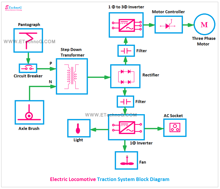
First, let's take a look at the block diagram of the Electric locomotive traction system, then we will discuss each block and the whole system.
How Does Electric Locomotive Traction System Work?
The above block diagram represents a Composite or Kando system means the locomotive takes a single-phase power supply from the overhead line and it converts into the three-phase supply and is used to operate the three-phase motor. Let's discuss each block, you will understand better.
Pantograph
The pantograph is a current collection system from the overhead line. The locomotive takes current from the overhead line through this pantograph. Pantographs are held up by compressed air pressure to connect with the overhead line. It is also designed to collapse if it detects an obstruction and can be manually down to isolate the locomotive from the overhead line.
Circuit Breaker
It is an electrical protective device. It is used to disconnect the locomotive from the main power supply coming through the pantograph when any fault occurs.
Axle Brush
Pantograph helps to connect phase or line conductor whereas axle brush helps to connect neutral conductor. We can say a locomotive takes current from the overload line through the pantograph and returns that current through the axle brush.
Step Down Transformer
In a Kando system, the locomotive is supplied by 16KV or 25KV, 50 Hz single-phase supply. So the step-down transformer is used to step down this high voltage. A tap changer is also used with this transformer.
Main Rectifier
The rectifier is used to convert the single-phase AC supply coming from the transformer into a DC supply. Generally, SCRs, IGBTs, etc are used for this rectifier because they carry a very high current and electrical power.
Filter
In the above diagram, you can see there are two Filters are used. These are the DC filters used to filter the DC output of the rectifier.
Three Phase Inverter
This single-phase to three-phase inverter is used to convert the DC supply (from the output of the rectifier) into a three-phase AC supply. This three-phase AC supply is used to operate the three-phase induction motor. Generally, high-power-carrying SCRs and IGBTs are used for this inverter circuit.
Motor Controller
The motor controller in an electric locomotive traction system is used to regulate the power delivered to the traction motors. It controls the locomotive's speed by adjusting the motor power and ensures smooth acceleration and deceleration by managing torque. It also protects the motors from overloading and overheating. Sometimes it can be used for directional control for forward and reverse movement.
Traction Motor
Generally, the modern locomotive system uses a three-phase asynchronous motor or induction motor. Induction motors provide very good speed regulation, regenerative braking, high acceleration, etc.
Single Phase Inverter
In the locomotive system, a single-phase inverter is also used which supplies power to Lights, Fans, AC Sockets, cooling fans, battery chargers, etc. This single-phase inverter also takes power from the main rectifier.
Read Also:
- Why Induction Motor cannot run at Synchronous Speed | Slip Phenomenon
- [BEST] Applications, Advantages, Disadvantages of Isolation Transformer
- Why Current, Voltage changes But Power, Frequency constant in Transformer?
- Advantages of both STAR and DELTA connection in Induction Motor
- [Explained] Transformer Size VS Frequency
[Explained] Electric Locomotive Traction System Block Diagram
![[Explained] Electric Locomotive Traction System Block Diagram](https://blogger.googleusercontent.com/img/b/R29vZ2xl/AVvXsEiXpiVCpKZV0ShfNbsTLYMv_BLvyUpOBBnZL0h7bVa3-3yVo1DtgdsB6gg09IbdYv4KFeUDQn-77NFohj2dFxkH1tpSl6pq3EGT3UVQM-CiQyPktJ0LaNpWZ6xz62Y0yQCtt-CrTZEE1sA/s72-c/Electric+Locomotive+Traction+System+Block+Diagram.png) Reviewed by Author
on
February 17, 2021
Rating:
Reviewed by Author
on
February 17, 2021
Rating:

