Direct Online Starter[DOL Starter] Diagram Full Explained
Direct Online Starter[DOL Starter]
In this post, we are going to know the details of each part of DOL Starter Diagram. All parts of the DOL starter Power Circuit Diagram and Control Circuit Diagram are explained. Direct Online Starter or DOL Starter is a very useful and commonly used AC Starter. DOL starters are mainly used with up to 5 H.P motors.
If you read the full article, then you will understand the DOL Starter Working Principle. I have explained the Working Principle of the DOL starter indirectly.
We know that electrical Motors should not be connected to the supply directly for many important reasons which are already explained in our old article. We use different types of AC Starter for starting purpose of AC Motors.
The concept of a simple DOL Starter:
A simple DOL Starter has mainly two parts, one is the Contactor and another is the Thermal Overload Relay. The Contactor is used for switching purposes and the thermal overload relay is used to prevent overcurrent faults. The DOL starter cannot reduce the voltage or current during the starting of the motor like other starters.
When we close the Contactor, the motor will get the power supply and it will start. When the motor draws overcurrent, the thermal overcurrent relay will trip the circuit, and the motor disconnects from the supply.
Actually, the DOL Starter which is used with a motor required additional circuits and equipment for its operation. In the above paragraph, only the basic concept is explained. Now we are going to know actually how the DOL starter is operated.
DOL Starter Circuit:
The whole DOL starter circuit is divided into two parts,
1. Power Circuit
2. Control Circuit
The connection or circuit to drive the motor is called the Power Circuit and the connection or circuit to operate the DOL starter is called the Control Circuit or Pilot Circuit.
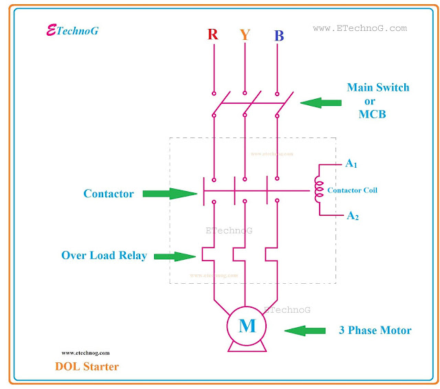
Diagram of the DOL Starter Power Circuit:
As you see in the above figure the DOL starter has two parts,
1. Contactor
2. Over Load Relay
In the power circuit, three devices or equipment are connected. First the Main switch. We mainly use MCB as the Main switch. Next, the Contactor is connected. The Overload Relay is connected after the Contactor. The output of the Relay is connected to the Motor.
When we buy any DOL Starter from the market, it has a Contactor and Overload Relay inside it. So we need an extra MCB or Main switch which should be connected before the Starter. The DOL Starter including a Control circuit also available in the market.
In the power circuit, we can only operate the Main switch or MCB, and the rest of all operations are done in the Control circuit.
Remember that the power circuit contains the full voltage like 230V for a single phase and 440V for a three-phase supply but the control circuit always contains up to 230V for a single-phase supply.
DOL Starter Control Circuit Diagram:
All main operations are done in the control circuit. The control circuit is connected to the Contactor Coil. When the coil of the Contactor is energized then the Contactor closes the power circuit and the Motor gets the power supply. So our main focus is to energize the coil of the Contactor. If you see the power circuit and the control circuit carefully then you will understand the operation of the DOL Starter.
As you see in the above diagram after turning ON the MCB when we push the Start push button switch the Contactor coil will be energized and the motor will start to run. After starting as the Contactor coil is energized the Hold on contact will be closed and it keeps ON the control circuit even after removing pressure on the Start Push Button switch.
You can see the Overload Relay operated switch is connected in series with the circuit which is Normally Closed. So when the motor draws overcurrent, the relay operated switch becomes open and the Contactor also disconnected the Motor from the supply.
The Overload indicator lamp is connected through an overload relay operated by a switch which is Normally Open so when the overload occurs, the Switch becomes closed and the Lamp will glow.
We can stop the Motor anytime by pressing the Stop push button switch which is Normally Closed.
As you see in the above figure the Power Circuit operates at 440V Three-phase supply and the control circuit operates 230V single-phase supply.
Read Also:
- Motor Control Circuit Forward Reverse | Wiring and Connection
- VFD Block Diagram, Applications, Advantages, Circuit, Panel
- Autotransformer Starter Diagram, Parts, Working Principle
- Soft Starter Wiring Diagram and Connection Procedure
- Double Motor Control with Selector Switch Connection
Thank you for visiting the website. keep visiting for more updates.
Direct Online Starter[DOL Starter] Diagram Full Explained
![Direct Online Starter[DOL Starter] Diagram Full Explained](https://blogger.googleusercontent.com/img/b/R29vZ2xl/AVvXsEgNvIeOYsp_j_K5vUpBDGH_iKWTlgeQqO71gFjXmV0fjUFCLh94HwAQ5QKKHIaJu25JZ8kzH_32_kx3YO1ebSS5i4BaDDElSHc7PMFKs4MlZR47gseP1oeyyBRWBAtcVZOHYCd_F4eC5r-0/s72-c/DOL+Starter+internal+parts.jpg) Reviewed by Author
on
February 15, 2019
Rating:
Reviewed by Author
on
February 15, 2019
Rating:

![Direct Online Starter[DOL Starter] internal parts Direct Online Starter[DOL Starter] internal parts](https://blogger.googleusercontent.com/img/b/R29vZ2xl/AVvXsEgNvIeOYsp_j_K5vUpBDGH_iKWTlgeQqO71gFjXmV0fjUFCLh94HwAQ5QKKHIaJu25JZ8kzH_32_kx3YO1ebSS5i4BaDDElSHc7PMFKs4MlZR47gseP1oeyyBRWBAtcVZOHYCd_F4eC5r-0/s640/DOL+Starter+internal+parts.jpg)

