Fan Regulator Connection Diagram and Internal Circuit Explanation
Fan Regulator Connection Diagram and Internal Circuit
A fan regulator is a very very much usable electrical or electronic device. We are all using the fan regulator in our house with Fan. Fan Regulator is a device by which we can control the speed of rotation of the fan. The basic principle of a fan regulator involves altering the voltage or current supplied to the fan motor, thereby changing its speed. Today we are going to know How fan regulator works, fan regulator internal circuit, and Fan Regulator Connection Diagram.
How Conventional Fan Regulator works?
This is Old Fan Regulator. As you see in the below figure, the construction of a conventional fan regulator is very simple. There is some series connected resistance that can be adjusted by rotating the knob of the regulator. This conventional fan regulator is to be connected in series with the fan and power supply. By moving the knob we can increase or decrease the resistance value. If we increase the value of resistance the voltage drop across the resistor will be increased so the voltage across the fan motor will be decreased and ultimately the speed of the fan will be decreased and Vice-versa.
click on the image to enlarge
The disadvantage of a Conventional Fan Regulator is that it causes a huge amount of heat loss or I2R loss because there are a number of resistors that cause heat loss across the resistors and eventually, this reduces the life of this regulator and also it affects your electricity bill so.
How does Electronic Fan regulator Work?
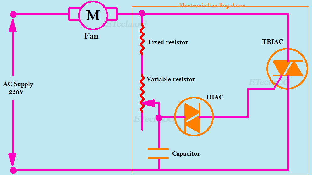
To reduce power loss nowadays electronic fan regulator is mostly used. Electronic fan regulator uses semiconductor devices.An electronic fan regulator has the following parts,
- TRIAC
- DIAC
- Capacitor
- Fixed resistor
- Variable resistor or Potentiometer
As you see in the below figure the TRIAC is connected in series with the Fan and the supply. The TRIAC can conduct AC current when a pulse signal is given to the gate terminal of the TRIAC. Here the DIAC is used to trigger the TRIAC. First, the capacitor will be charged through the fixed and variable resistor resistors. When the capacitor is fully charged it starts discharging through the DIAC. Now the TRIAC will be triggered and it starts conducting, therefore, the current will flow from the supply through the TRIAC and the fan.
Actually, the TRIAC remains ON for a short time duration and remains OFF for a short time duration according to the charging and discharging of the Capacitor. This process causes to reduction in the value of the average voltage across the Fan and ultimately the speed of the fan will be decreased.
The variable resistor or potentiometer is used to change the time constant of the capacitor. That means when we increase the resistance by moving the potentiometer knob the charging time of the capacitor will be increased and this causes the TRIAC to remain OFF for more time. This process causes to more decrease in the value of the average voltage across the fan and the speed of the fan also more decreased.
The fixed resistor is used to protect the capacitor from the full voltage. That means if we did not use the fixed resistor the full voltage will appear across the capacitor if we decrease the variable resistance to zero that may damage the capacitor
Internal Circuit of Fan regulator:
Here the internal circuit diagram of an electronic fan regulator is shown below
click on the image to enlarge
Fan regulator connection Diagram:
Here two-way switches are connected with the regulator but you can use a normal switch.click on the image to enlarge
Connection Procedure
- Take the power supply wire (usually the live wire) and connect it to the input terminal of the fan regulator. Secure the connection tightly.
- Locate the two wires that connect the two-way switches. These wires usually have different colors or are marked with indicators such as 'L1' and 'L2'. Connect one switch wire to the output terminal of the fan regulator. Use a wire nut or suitable connector to make a secure connection.
- Locate the wire that connects the switches to the fan. This wire is typically connected to the common terminal of the two-way switches. Connect this wire to the motor terminal of the fan.
After completing the connections and ensuring everything is secure, switch on the power supply from the main electrical panel and Test the fan regulator by operating the switches.
Read Also:
- [Explained] Connection of Tube Light with Diagram
- Electrical Switch Board Connection Diagram and Wiring
- Electrical Extension Board Connection Diagram and Wiring
- [Proper] Ceiling Fan Connection with Regulator, Switch, and Capacitor
- [Proper] Two-Way Switch Connection Diagram and Wiring
Thank you for visiting the website. keep visiting for more updates.


